Back: (y-03) GPU Architecture | Next: (y-05) Shading Models | RTG Index
Mental Model First: Geometry as Data
- Objects become triangles. The GPU is built around simple primitives that can be transformed, rasterized, and interpolated efficiently.
- Transforms are matrix products. Movement through object, world, camera, clip, and screen spaces is mostly linear algebra.
- Rasterization is inside testing plus interpolation. Edge equations decide coverage; barycentric coordinates carry attributes across the triangle.
- Visibility is an order test. The depth buffer does not need exact metric depth, only a value that preserves near/far ordering.
1. Object Order and Triangle Data
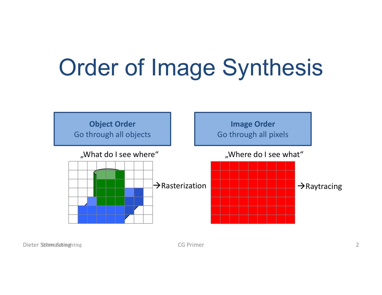
L04_Pg-02: Object-order image synthesis visits objects and projects their primitives to the screen.
Computer graphics usually starts from scene geometry, not from pixels. The renderer projects objects into the image and lets rasterization find the covered samples.
Indexed Triangles
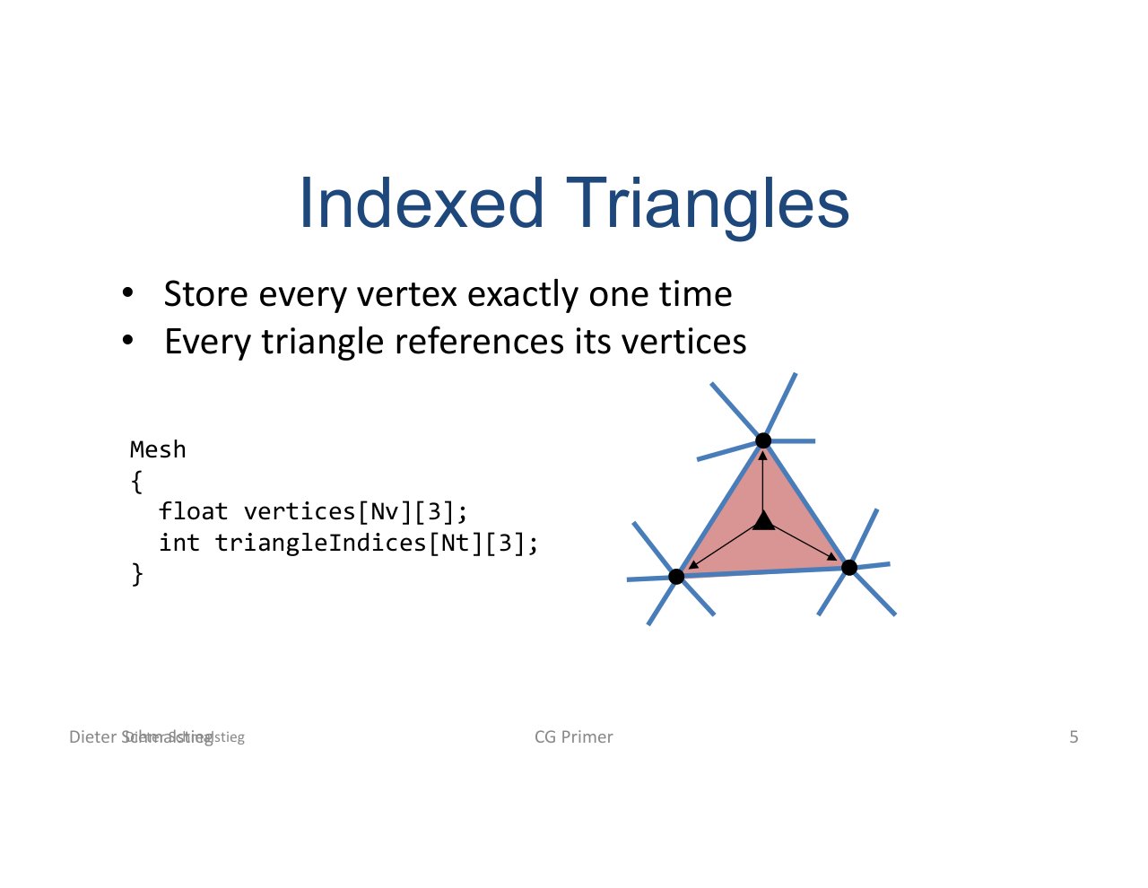
L04_Pg-05: Indexed triangles store each vertex once and reference it from multiple triangles.
A triangle soup duplicates vertices for every triangle. Indexed geometry stores shared vertices once, then uses an index buffer to define triangles. This reduces memory and improves vertex reuse.
2. Transformation Pipeline
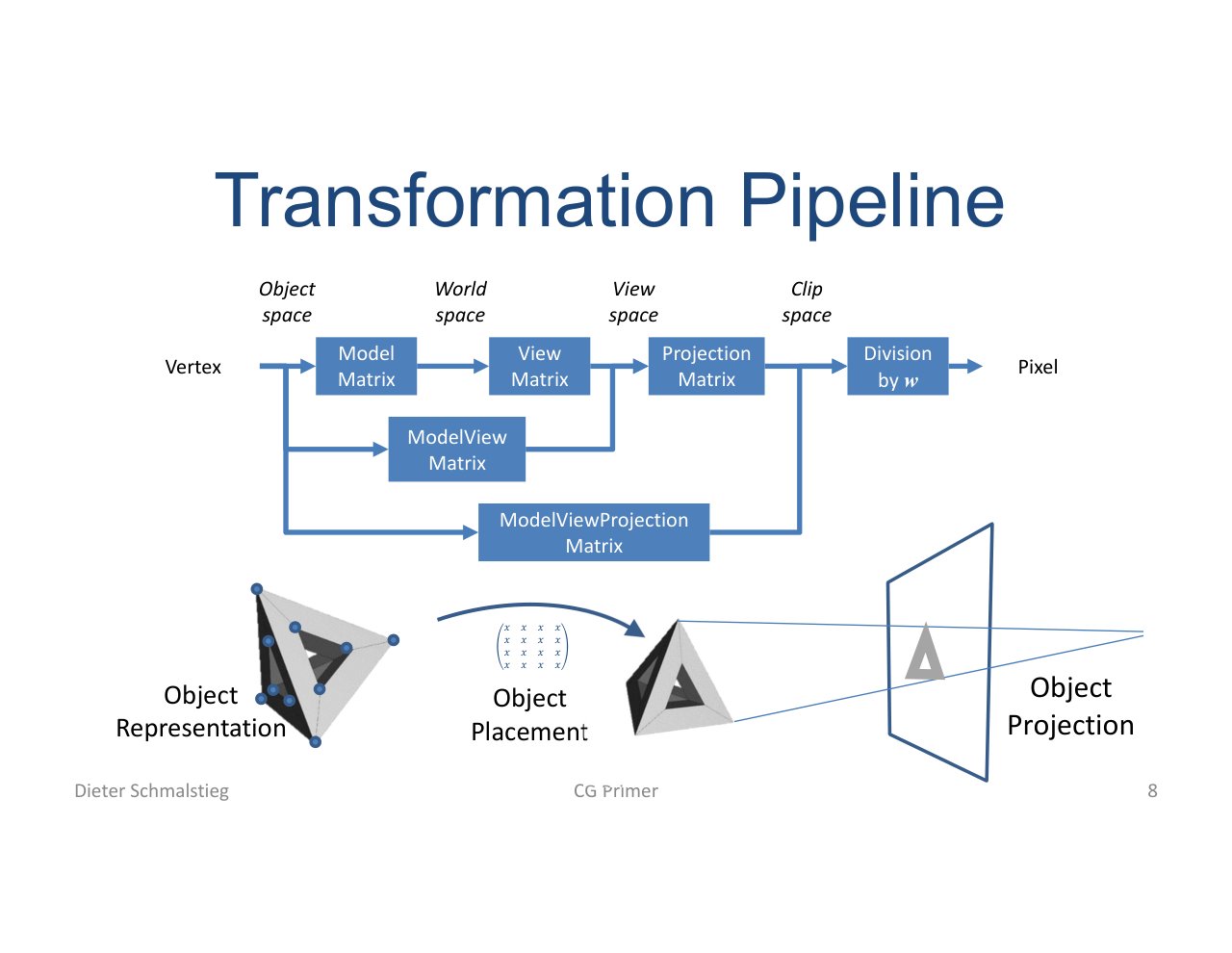
L04_Pg-08: Vertices move from object space through world, camera, clip, normalized device, and viewport spaces.
The standard chain is:
- Object space: local model coordinates.
- World space: object placed in the scene.
- Camera space: coordinates relative to the camera.
- Clip space: projection applied; clipping can happen.
- Normalized device coordinates: after perspective divide.
- Viewport space: final screen coordinates.
Homogeneous Coordinates
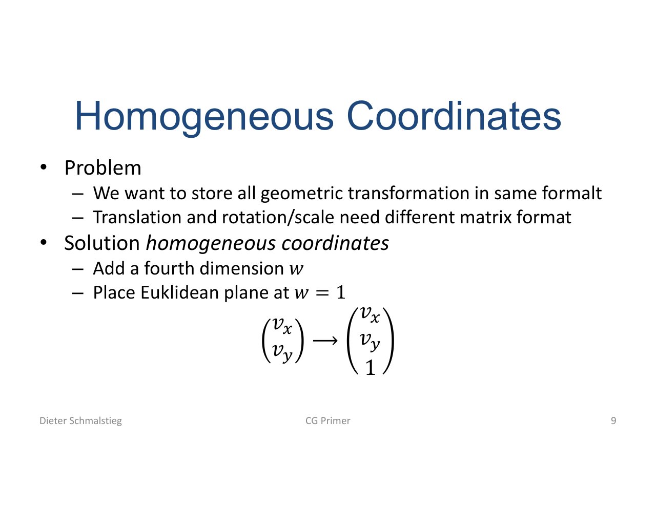
L04_Pg-09: Homogeneous coordinates add a w component so affine transforms and projection fit into matrix form.
The fourth coordinate lets translation, scaling, rotation, and projection share the same representation:
For points, . After projection, the hardware divides by to return to 3D normalized coordinates.
3. Core Transform Matrices
Translation
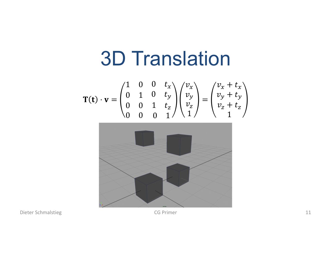
L04_Pg-11: Translation moves a point by storing offsets in the fourth column of a homogeneous matrix.
Translation is not linear in 3D coordinates alone, but it becomes a matrix multiplication in homogeneous coordinates.
Scaling
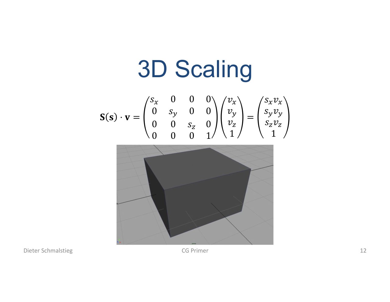
L04_Pg-12: Scaling stretches coordinates along each axis.
Scaling changes object size. Non-uniform scaling can distort normals, which matters later for lighting.
Rotation
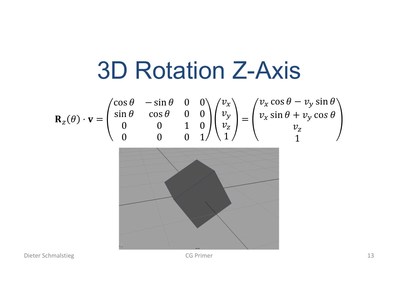
L04_Pg-13: Rotation matrices change orientation while preserving distances around the chosen axis.
Rotation order matters because matrix multiplication is not commutative. Rz * Ry * Rx generally differs from Rx * Ry * Rz.
🧠 Deep Dive: Explicit Matrix Forms
For reference (column-major, applied as ):
Translation by :
Scale by :
Rotation about the principal axes by angle :
Composition order: read right-to-left as “apply to the vector first”. scales the model, then rotates, then translates. Reverse that order and the object rotates around the world origin instead of its own centre.
Inverse of a rigid transform : the inverse is - the transpose of the rotation plus the translated origin. This is the standard view-matrix construction: rotate the world into camera frame, then translate the camera to the origin.
4. Projection and Camera Space
Perspective Projection
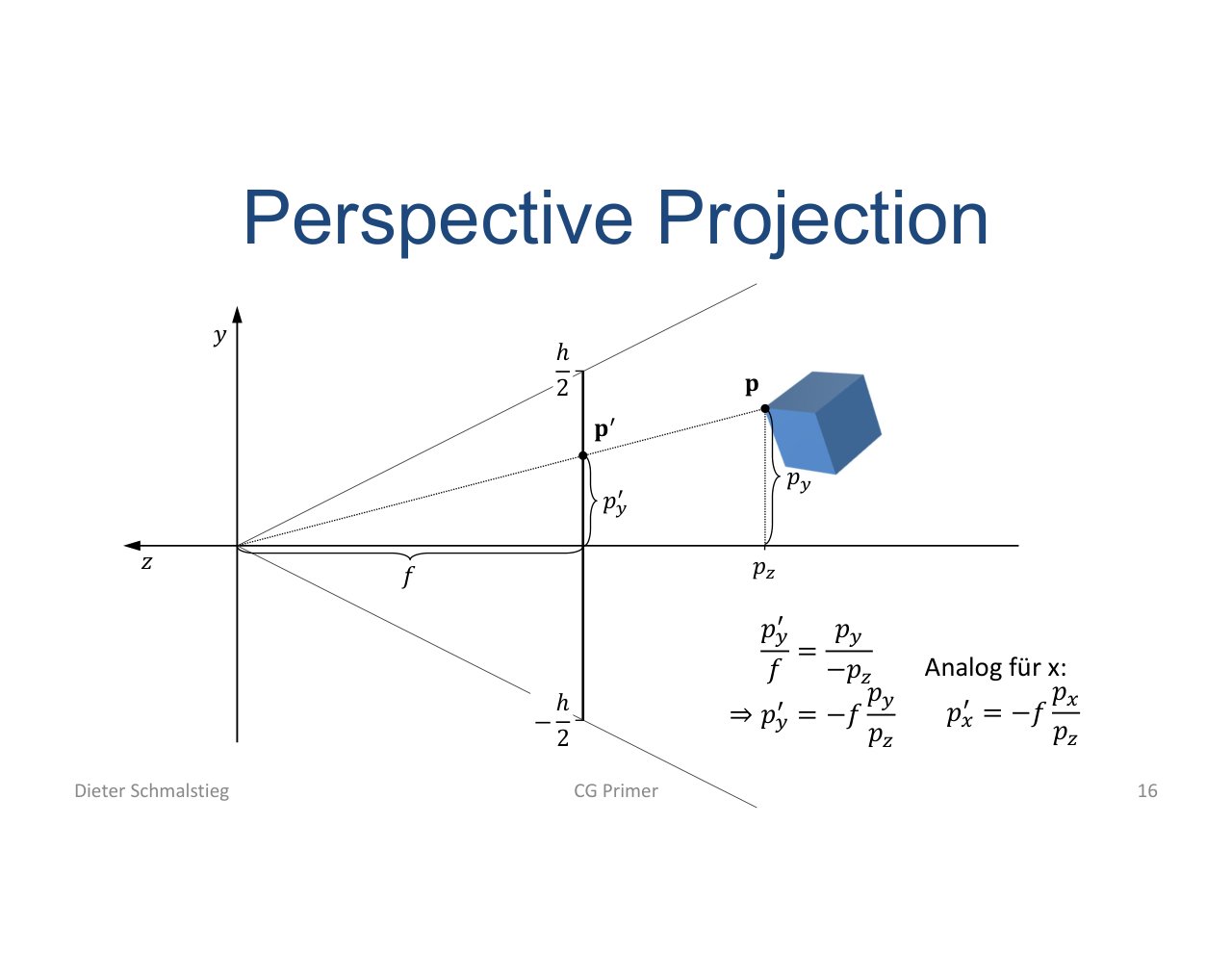
L04_Pg-16: Perspective projection makes farther objects appear smaller by preparing coordinates for division by depth.
Perspective projection encodes the camera frustum. The visual effect comes from the later divide by , not from a simple 2D scale.
Normalization of Homogeneous Coordinates
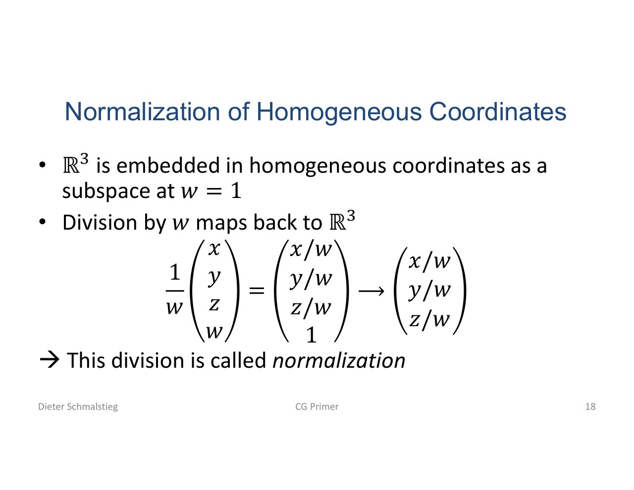
L04_Pg-18: Dividing by w maps homogeneous coordinates back into ordinary 3D coordinates.
All nonzero scalar multiples of a homogeneous point represent the same Euclidean point. Normalization picks the representative with .
Camera Transformation
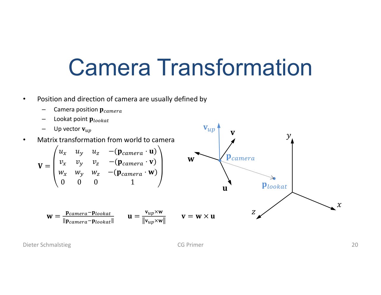
L04_Pg-20: The camera transform is built from camera position, direction, and up vector.
The view matrix can be understood as moving the world so the camera becomes the origin looking down its canonical direction.
Normalized Device Coordinates
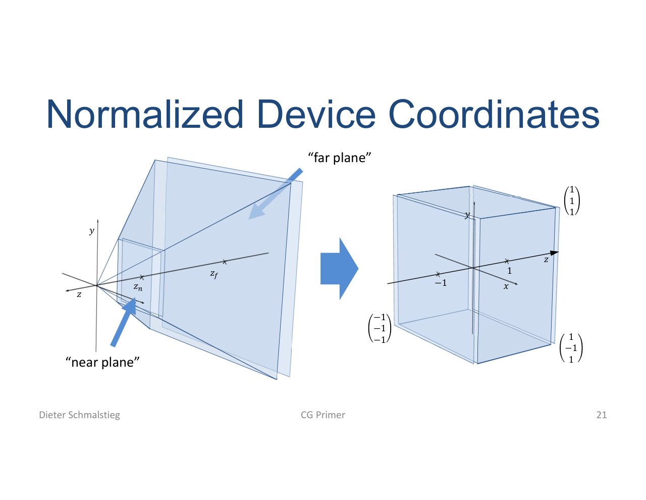
L04_Pg-21: After perspective division, visible geometry lies inside normalized device coordinates.
NDC is the canonical space used before viewport mapping. It makes screen mapping independent of the actual window size.
5. Culling, Clipping, and Rasterization
Culling and Clipping
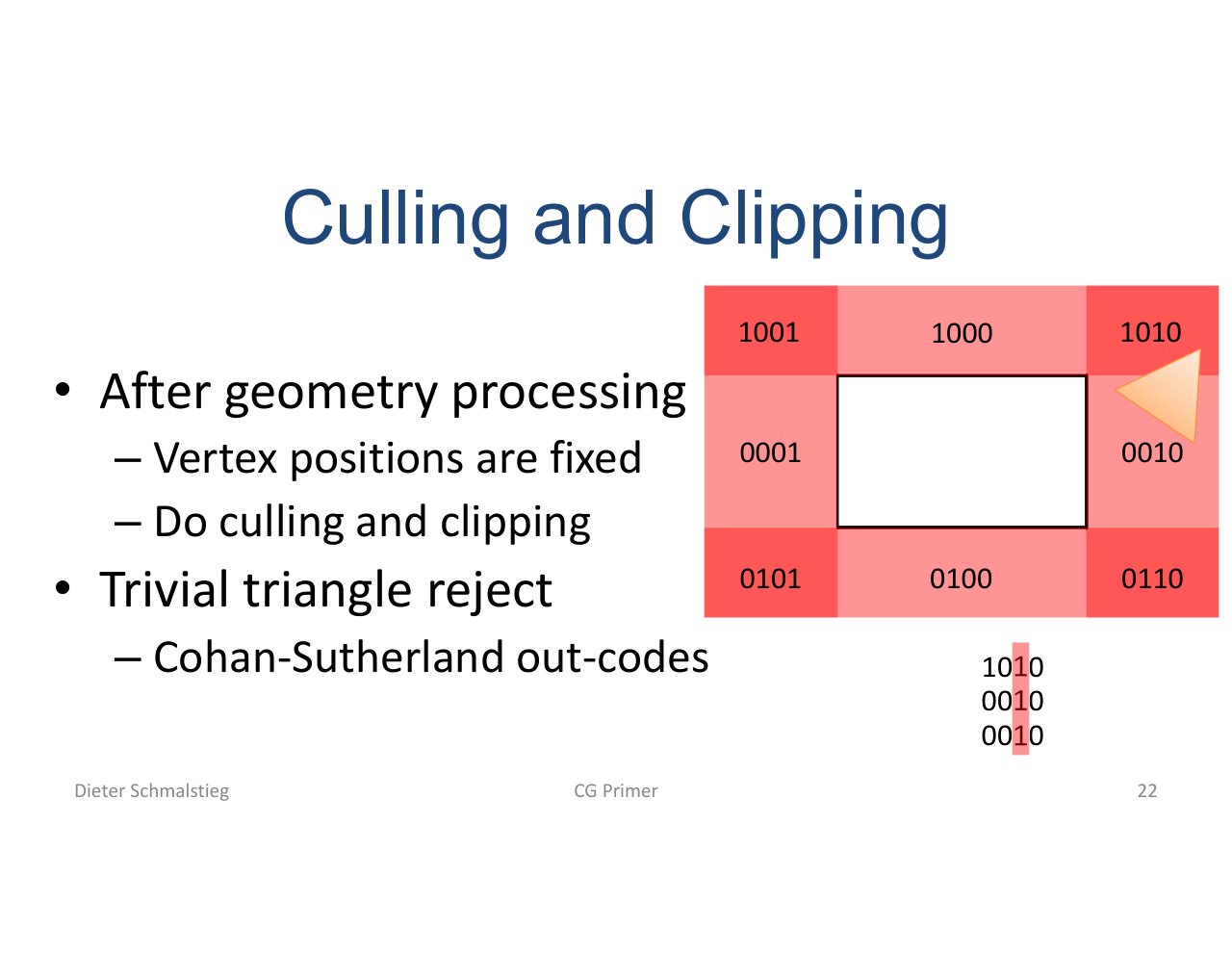
L04_Pg-22: Culling rejects fully invisible geometry; clipping handles primitives that cross the visible boundary.
Rejecting invisible primitives early protects later stages from unnecessary work.
Rasterization and Edge Equations
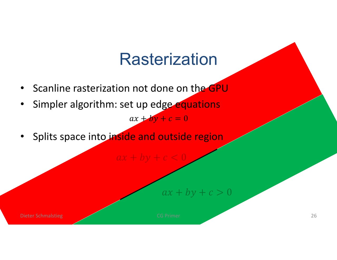
L04_Pg-26: Rasterization uses edge equations to decide whether samples lie inside a triangle.
Each triangle edge defines a half-plane. A sample is inside when it lies on the correct side of every edge.
Hierarchical Rasterization
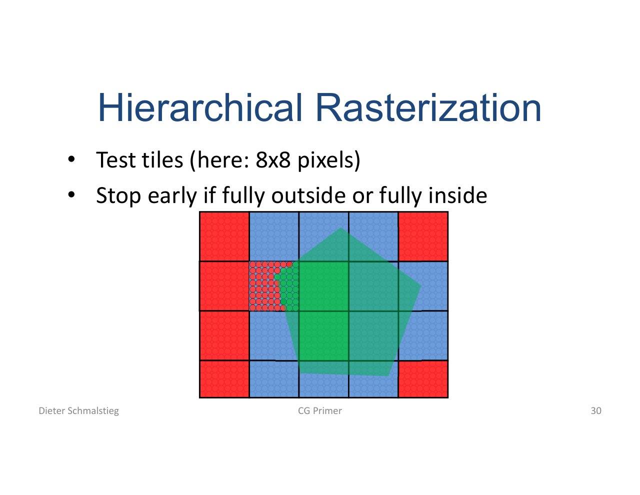
L04_Pg-30: Hierarchical rasterization tests tiles before individual samples.
Tile-level tests are a throughput optimization: large fully inside/outside regions can be accepted or rejected without checking every pixel first.
6. Depth and Visibility
Depth as an Order Relation
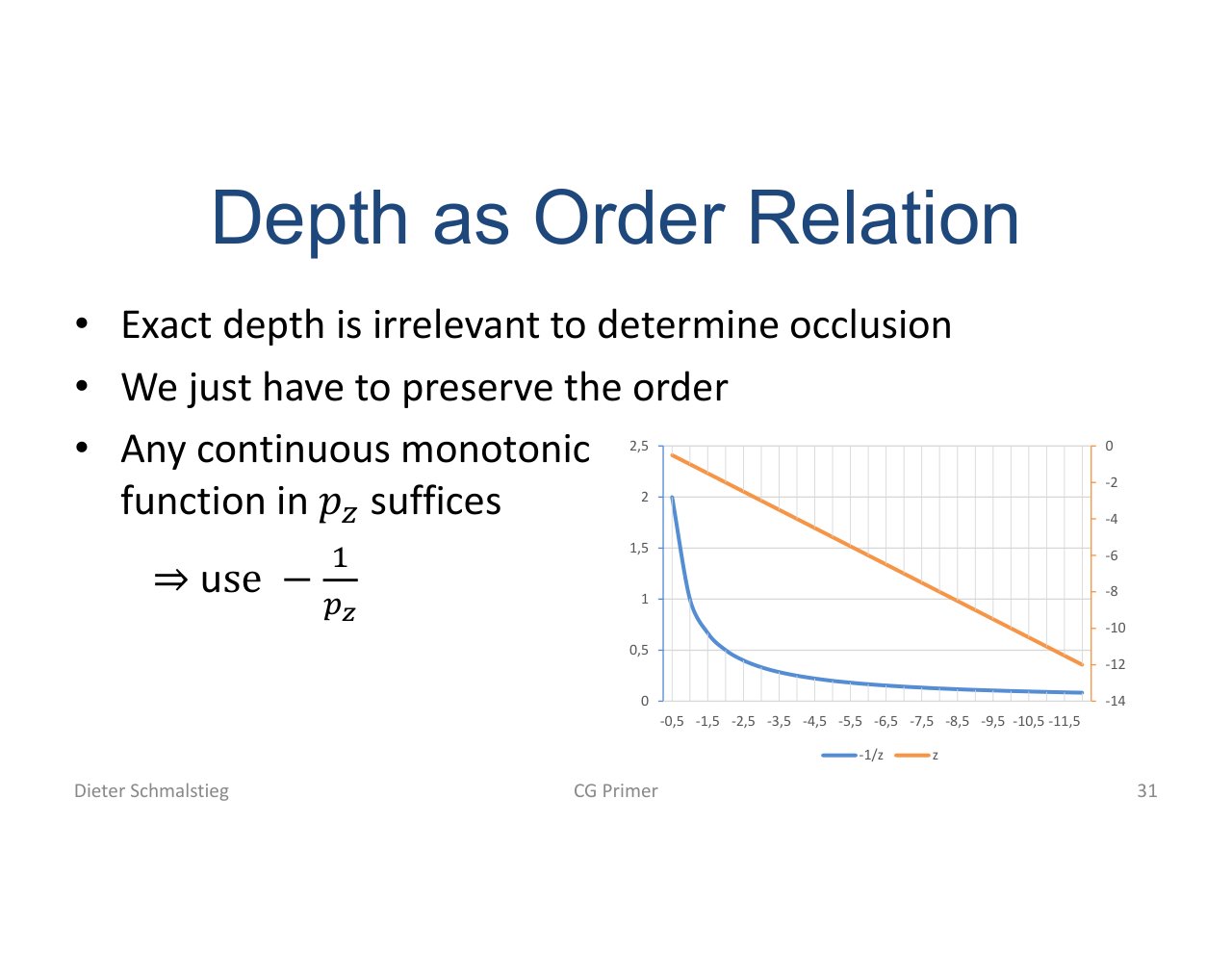
L04_Pg-31: Depth values only need to preserve visibility ordering, not physical distance linearly.
The depth buffer answers: which fragment is closer? A nonlinear projection is acceptable if the ordering is correct and precision is sufficient.
Depth Buffer Algorithm

L04_Pg-35: The z-buffer stores the nearest depth per pixel and updates it when a closer fragment arrives.
This avoids sorting all triangles by depth. The GPU can draw primitives in arbitrary order and let the depth test resolve visibility.
7. Shading and Material Basics
Lambert Shading
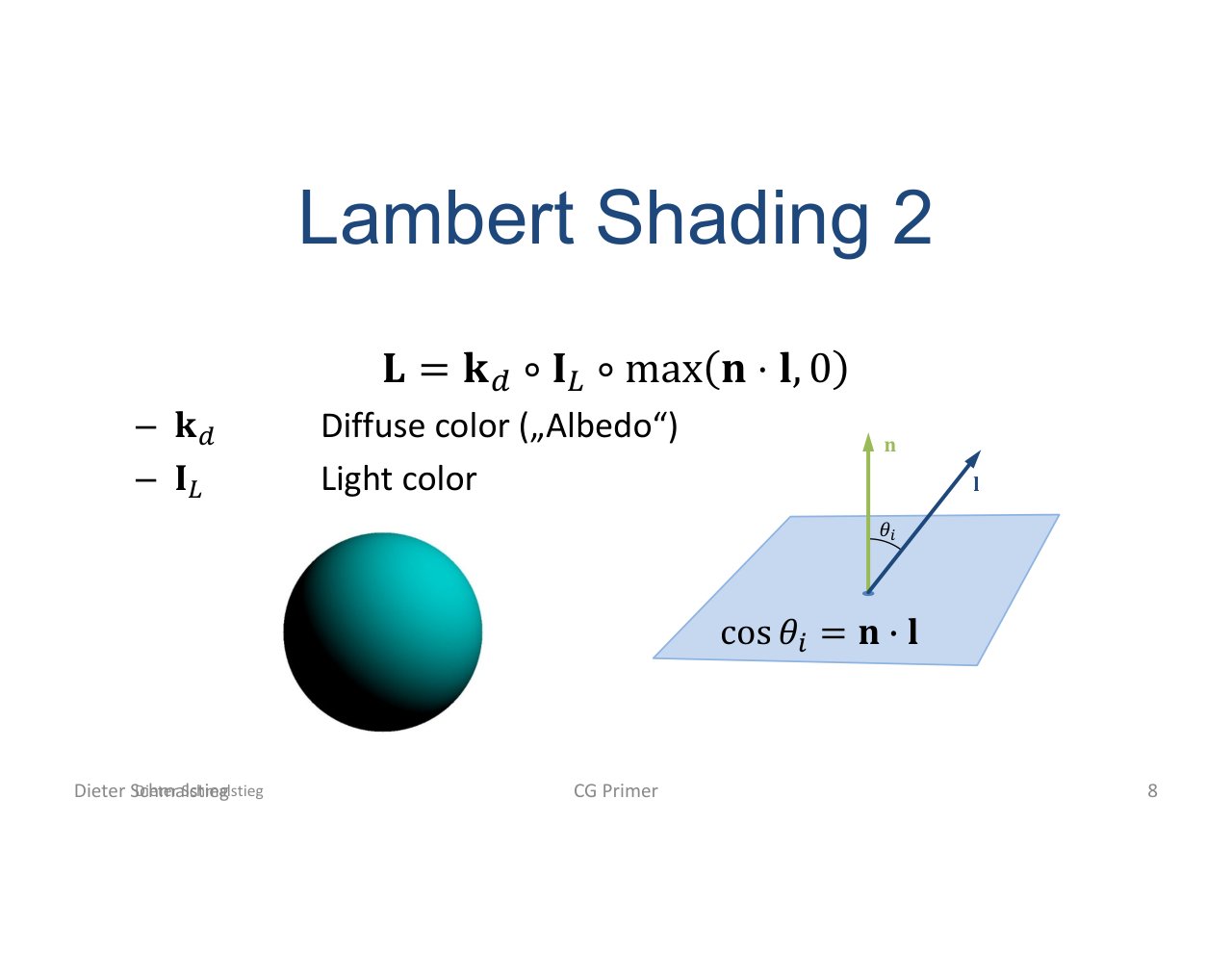
L04_Pg-37: Lambert shading uses the dot product between surface normal and light direction for diffuse light.
The basic diffuse term is:
It is view-independent: rotating the camera does not change the brightness if light and surface orientation stay fixed.
Phong Shading
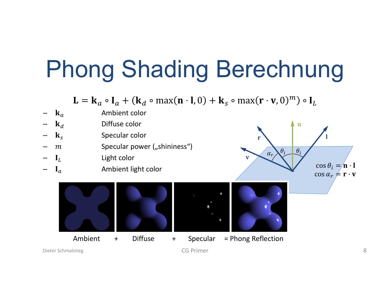
L04_Pg-38: Phong shading adds ambient, diffuse, and specular terms.
Phong introduces a view-dependent highlight. It is useful as a first specular model, even though the next lecture explains why it is not physically accurate.
8. Textures and Interpolation
Textures
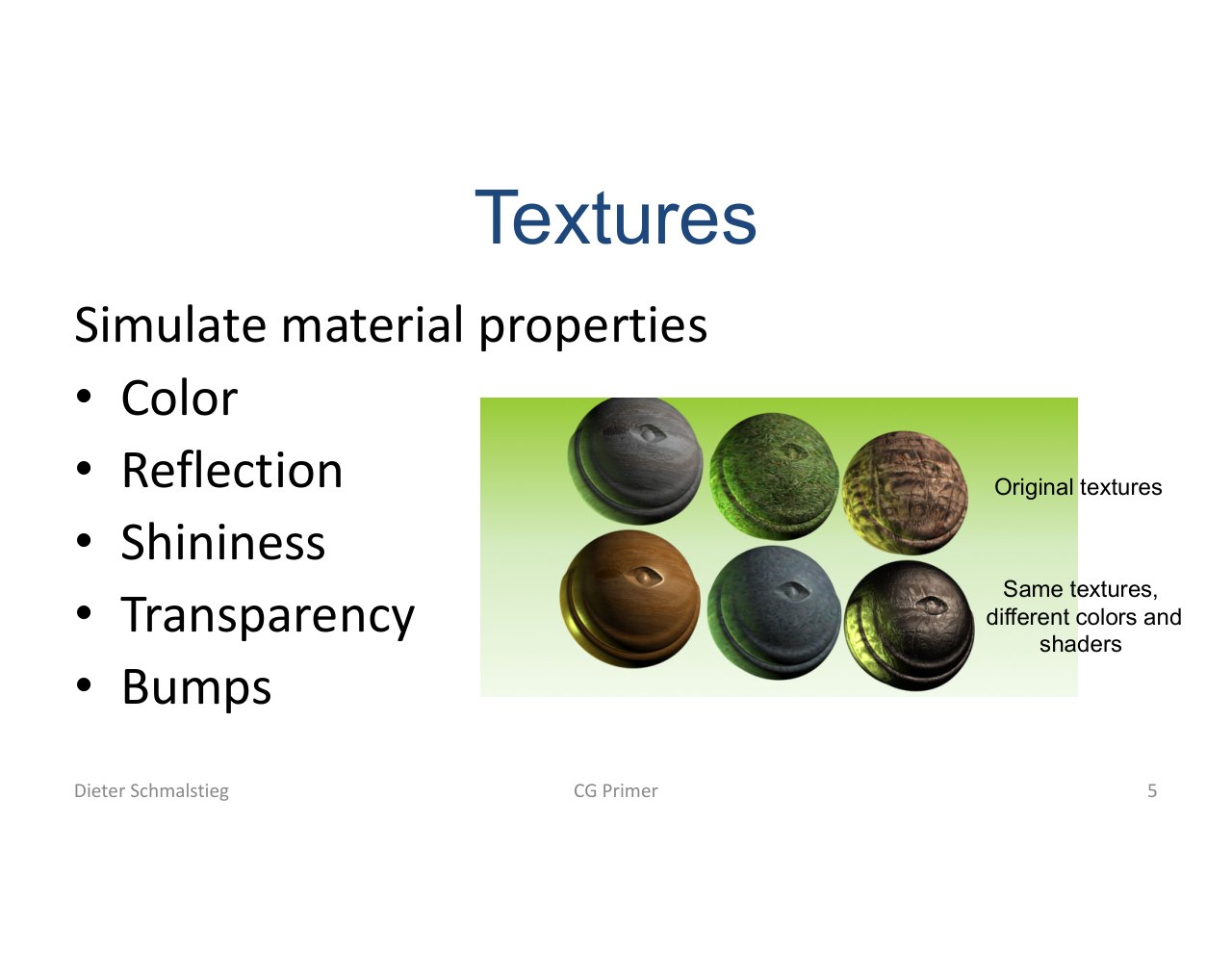
L04_Pg-39: Textures simulate spatially varying material properties such as color, reflection, and shininess.
Textures let one mesh reuse the same geometry while changing appearance across the surface.
Texture Coordinates
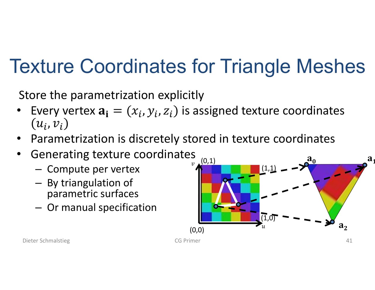
L04_Pg-41: Texture coordinates attach a 2D parameterization to mesh vertices.
Each vertex stores coordinates. Rasterization interpolates them for fragments, and the fragment shader samples the texture.
Barycentric Coordinates
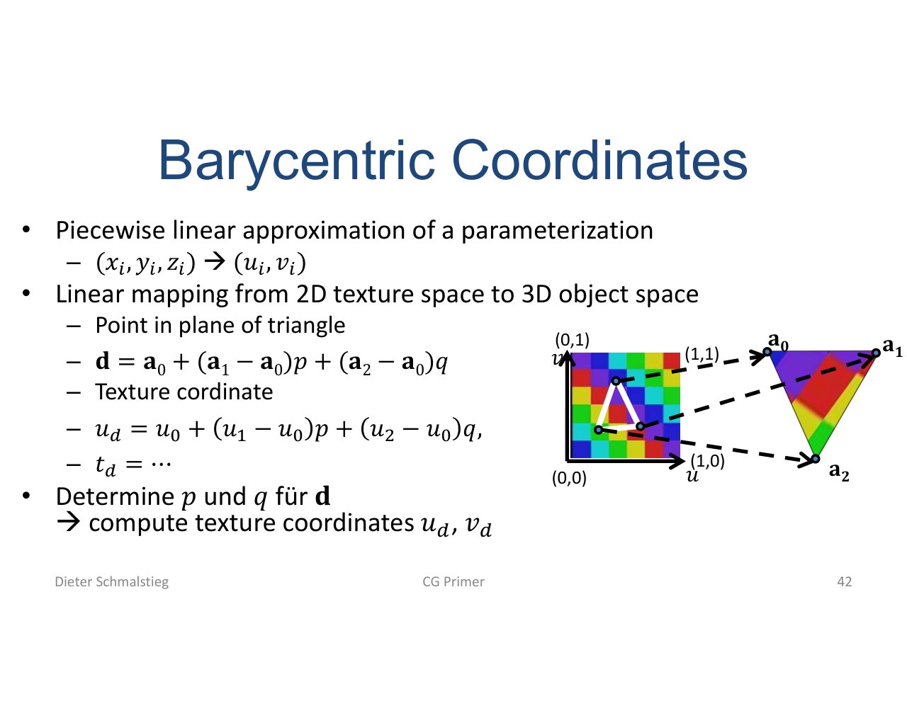
L04_Pg-42: Barycentric coordinates express a point inside a triangle as weighted vertex contributions.
For a point inside a triangle:
The same weights interpolate colors, normals, texture coordinates, and other vertex attributes.
Alpha Blending
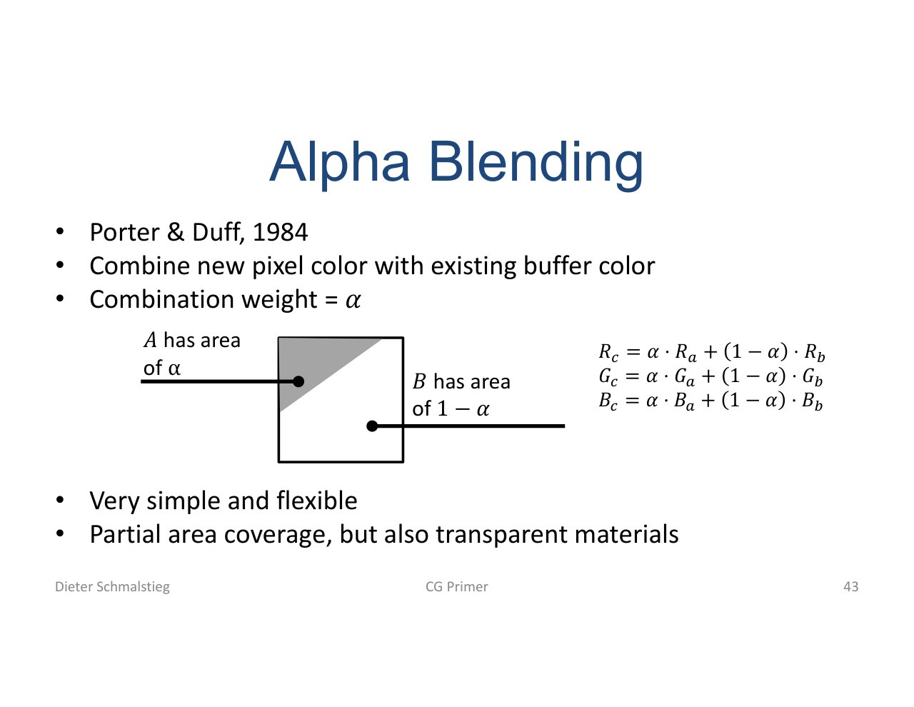
L04_Pg-43: Alpha blending combines the new fragment color with the existing framebuffer color.
Transparency is order-dependent. Correct alpha blending usually requires drawing transparent objects from back to front after opaque objects.
Applied Exam Focus
- Spaces in order: object -> world -> camera -> clip -> NDC -> viewport.
- Homogeneous coordinates: know why the fourth coordinate makes translation and projection matrix-based.
- Perspective divide: understand that perspective comes from dividing by .
- Rasterization: connect edge equations, barycentric coordinates, and interpolation.
- Depth buffer: explain why unsorted triangles can still produce correct visibility.
- Alpha blending: remember that transparent rendering is order-dependent.
Self-Check
- Why do we use 4D homogeneous coordinates instead of plain 3D coordinates?
Answer
A 4x4 matrix can encode translation, rotation, scale, and perspective uniformly, but only because the extra coordinate exists. Translation is not linear in 3D, so it cannot be expressed by a 3x3 matrix; in 4D it slips into the matrix column for . Perspective then arises from dividing by the resulting after the matrix multiply.
- What is the difference between clip space, NDC, and viewport coordinates?
Answer
Clip space is the result of the projection matrix, with still present, and clipping happens there. After dividing by , the visible region lies in normalized device coordinates, a canonical cube independent of window size. The viewport transform then maps NDC into actual pixel coordinates for the framebuffer.
- Write the Lambert diffuse formula and explain why it is view-independent.
Answer
. The light intensity depends only on the surface normal and the light direction , not on the view direction. Rotating the camera does not change the dot product, so the diffuse brightness stays the same regardless of where the camera looks from.
- How does the rasterizer decide whether a sample is inside a triangle, and how does it interpolate attributes?
Answer
Each triangle edge defines a half-plane; a sample is inside iff it lies on the correct side of all three edges (the edge-equation test). For samples that pass, barycentric coordinates with express the sample as a weighted combination of the vertices, and the same weights interpolate per-vertex color, normal, and texture coordinates.
- Why does the depth buffer remove the need to sort opaque triangles, but not transparent ones?
Answer
For opaque triangles the depth test keeps the closest fragment per pixel regardless of submission order. For transparent fragments the blend equation depends on the order in which fragments are applied to the framebuffer; back-to-front compositing of transparent objects is needed to get the correct color, which sorting (or order-independent transparency techniques) provides.
- In what order should the model, view, and projection matrices be combined to transform a model-space vertex into clip space, and why?
Answer
. Read right-to-left: places the model into world space, moves the world into camera space, and projects into clip space. Matrix multiplication is not commutative, so swapping the order produces a different transform (e.g. vs generally give different camera-space positions). Engines usually precompute once per object and submit it as a uniform.
- How is the camera (view) matrix typically constructed from a camera position , target , and world-up ?
Answer
Build an orthonormal camera frame: forward , right , up . The view matrix rotates the world so this frame becomes axis-aligned, then translates so moves to the origin. In matrix form, where has as columns (the is because OpenGL’s camera looks down ).
- Why is non-uniform scaling problematic for surface normals, and how is the issue fixed?
Answer
Transforming a normal with the same matrix as positions distorts it under non-uniform scale: a normal on a flat surface stays even if the surface is squashed along , which is wrong. The correct transform is the inverse transpose of the upper-left submatrix of the model matrix, applied to the normal and then renormalized. For uniform scale the inverse transpose equals the original rotation, so the issue only matters when the model has stretched axes.
Back: (y-03) GPU Architecture | (y) Back to RTG Index | Next: (y-05) Shading Models