Back: (y-05) Shading Models | RTG Index | Next: (y-07) Deferred Shading
Mental Model First: Textures as Functions
- A texture is a lookup function. Most textures are 2D images, but the shader only sees a function evaluated for each fragment.
- Texture coordinates are the contract between geometry and pixels. The mesh supplies , the sampler decides how to read nearby texels, and the fragment shader decides what the value means.
- Filtering is part of correctness, not polish. When one screen pixel covers many texels, naive lookup aliases; when texels are too sparse, naive magnification blocks.
- Advanced effects reuse the same idea. Light maps, cube maps, bump maps, normal maps, and projective textures are all texture lookups with different coordinate generation and interpretation.
1. What Textures Add
Why Texturing?
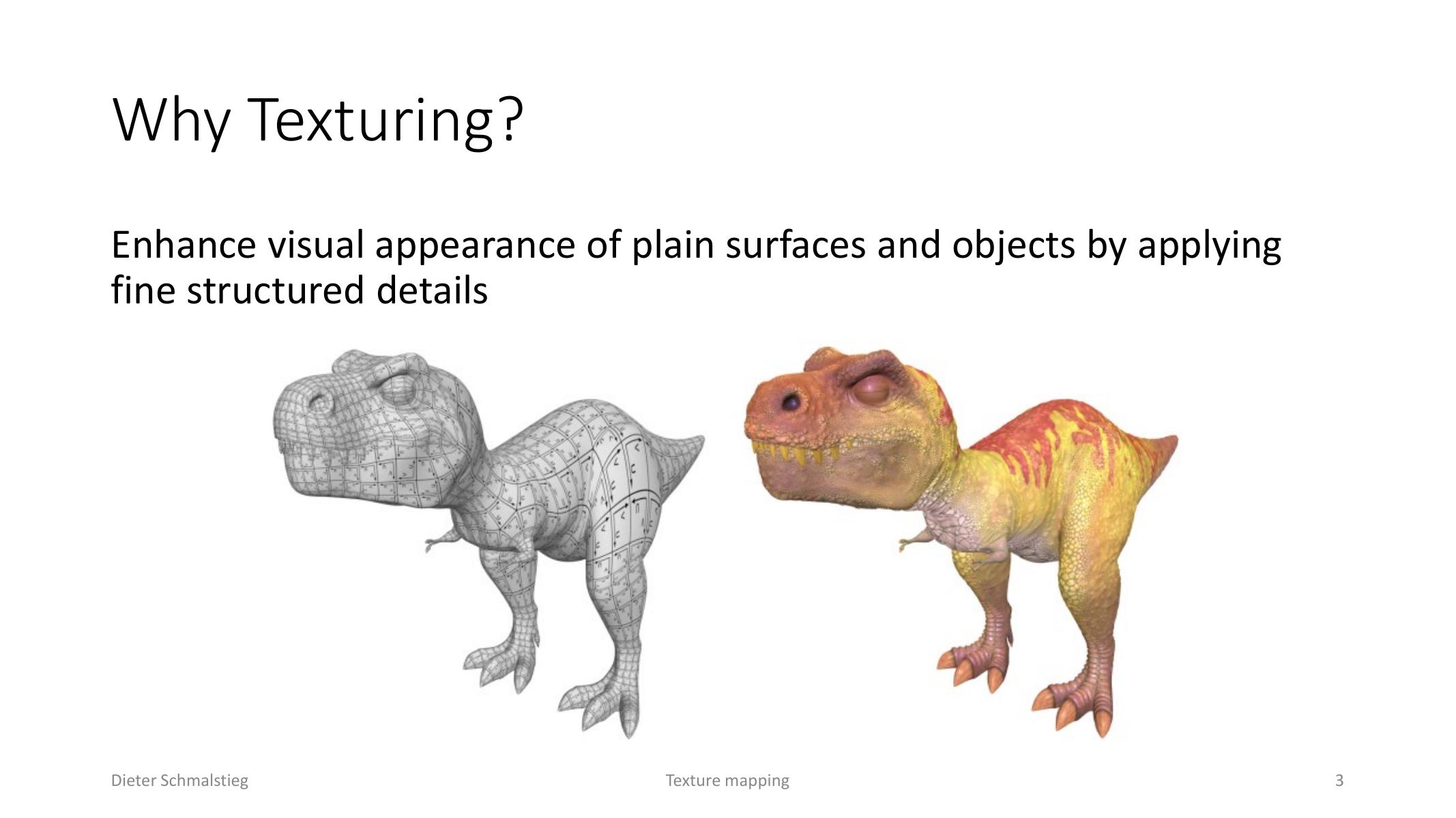
L06_Pg-03: Textures add fine structured detail without adding equivalent geometric complexity.
Texturing adds fine detail to otherwise simple geometry. Instead of modeling every small color change, groove, reflection patch, or transparent region as geometry, the renderer stores variation in a texture and evaluates it in the fragment shader.
Texture as Data
L06_Pg-04: A texture is a function evaluated for each fragment; the shader decides what the fetched data means.
A texture provides the look and feel of a surface. It is usually a 2D raster image, but the important definition is broader: a texture is a function evaluated per fragment, and its data can represent arbitrary information.
The same texture can drive different material properties depending on the shader:
- color or albedo,
- reflection and gloss,
- transparency,
- bump or normal perturbation,
- procedural or simulation values.
Texture Types
L06_Pg-06: Textures can be 1D functions, 2D surface maps, or 3D volumes.
Textures can be one-dimensional, two-dimensional, or three-dimensional:
- 1D textures replace a linear value in the shader, such as using a toon ramp instead of continuous lighting.
- 2D textures attach image-like data to surface coordinates and are the common case for color, height, glossiness, and opacity maps.
- 3D textures represent a volume , useful for solid procedural materials and sampled volumes.
2. Texture Coordinates and Parametrization
Texture Coordinates
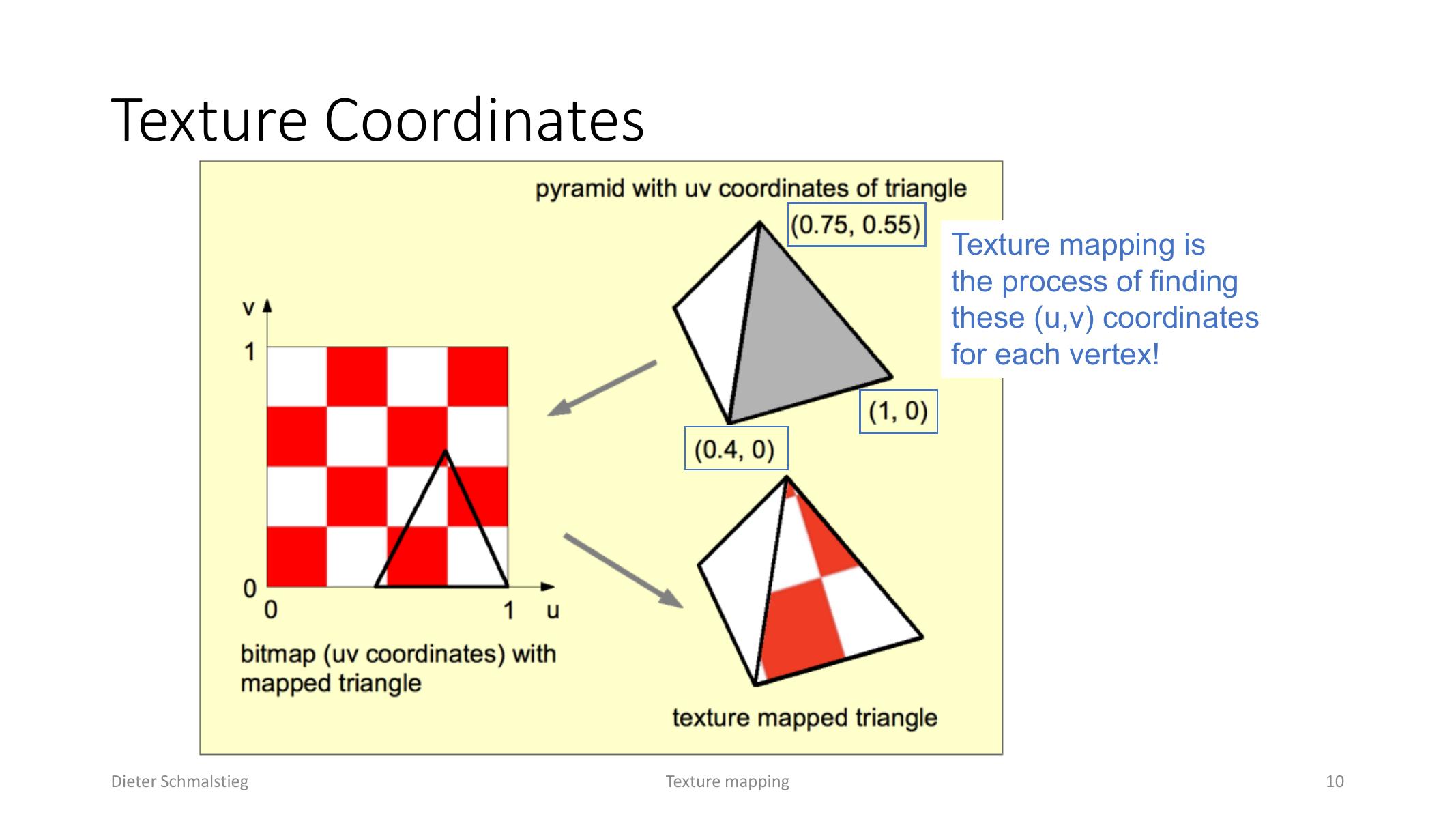
L06_Pg-10: Texture mapping finds the surface coordinate used to sample the texture for each vertex and fragment.
Texture mapping is the process of finding the right coordinate for each vertex and interpolating it across the primitive. The rasterizer then gives the fragment shader a texture coordinate for each covered pixel.
Analytic Parametrization
Simple analytic mappings derive texture coordinates from geometry:
- Planar mapping drops one object coordinate. It is simple but only looks good from one direction.
- Cylindrical and spherical mapping compute angles around the object center, similar to polar or spherical coordinates.
- Box mapping projects onto cube-like faces and is mainly useful for environment mapping.
These mappings can introduce distortion and singularities. Real assets are often manually unwrapped in modeling software so texture space follows the artist’s intended seams and density.
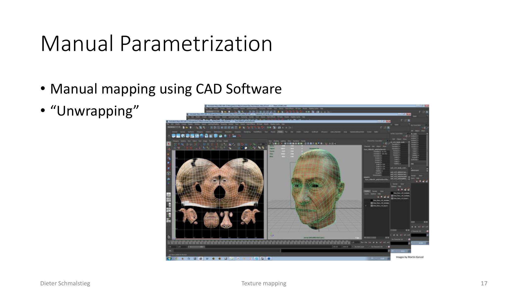
L06_Pg-17: Manual unwrapping lets artists correct distortions and place texture seams intentionally.
Texture Addressing
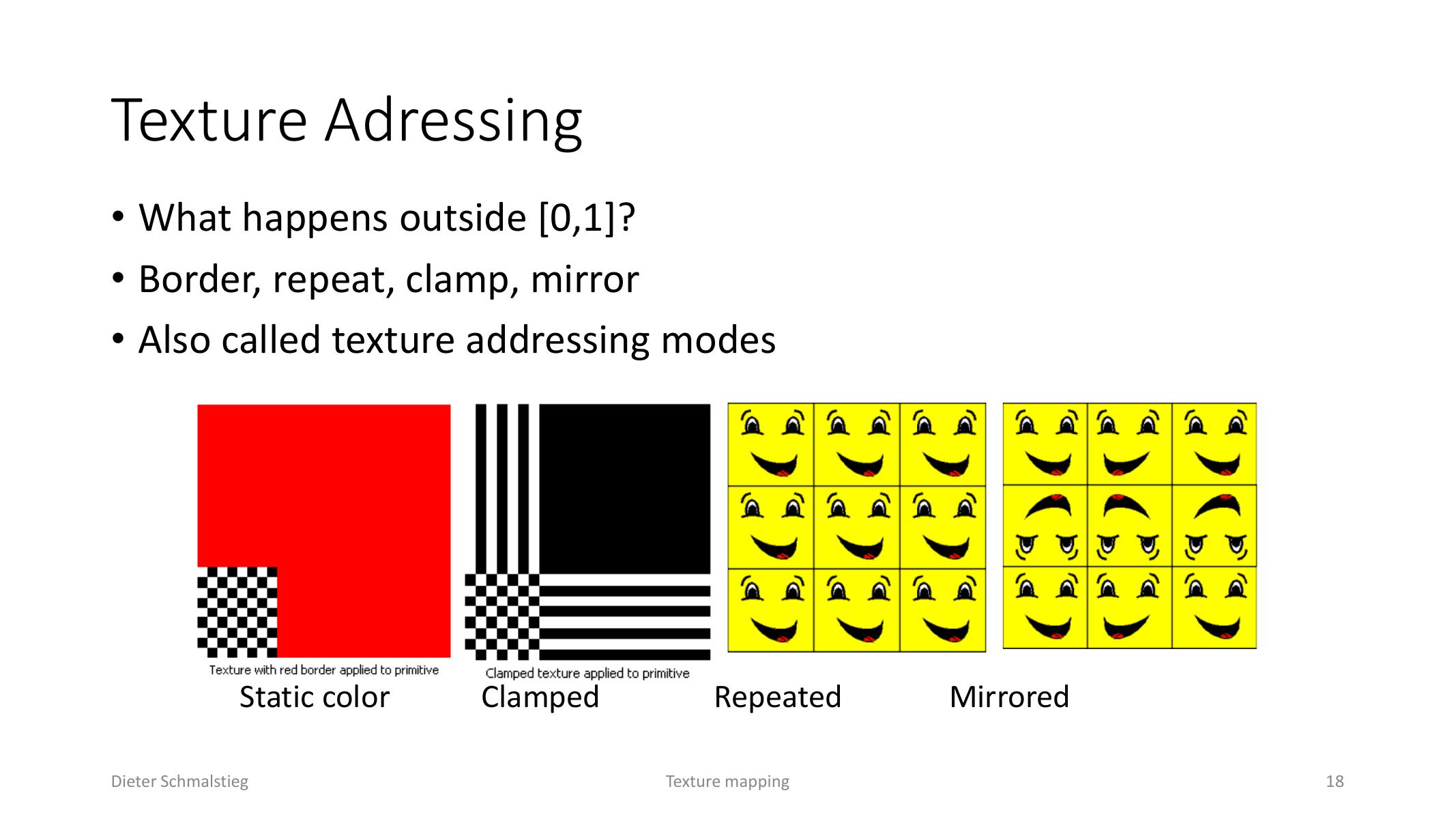
L06_Pg-18: Addressing modes define samples outside the [0,1] coordinate range.
The sampler must define what happens when coordinates leave the canonical range. Common addressing modes are:
- border/static color,
- clamp,
- repeat,
- mirror.
Repeated and mirrored modes are useful for tiled materials; clamping is useful when sampling should stay at the edge.
3. Texture Data on the GPU
Texture Compression
Texture compression reduces memory bandwidth and storage. S3TC stores a texel block using two 16-bit colors plus 2-bit per-texel indices into interpolated colors, giving roughly 4:1 or 6:1 compression.
Texture Objects and Samplers
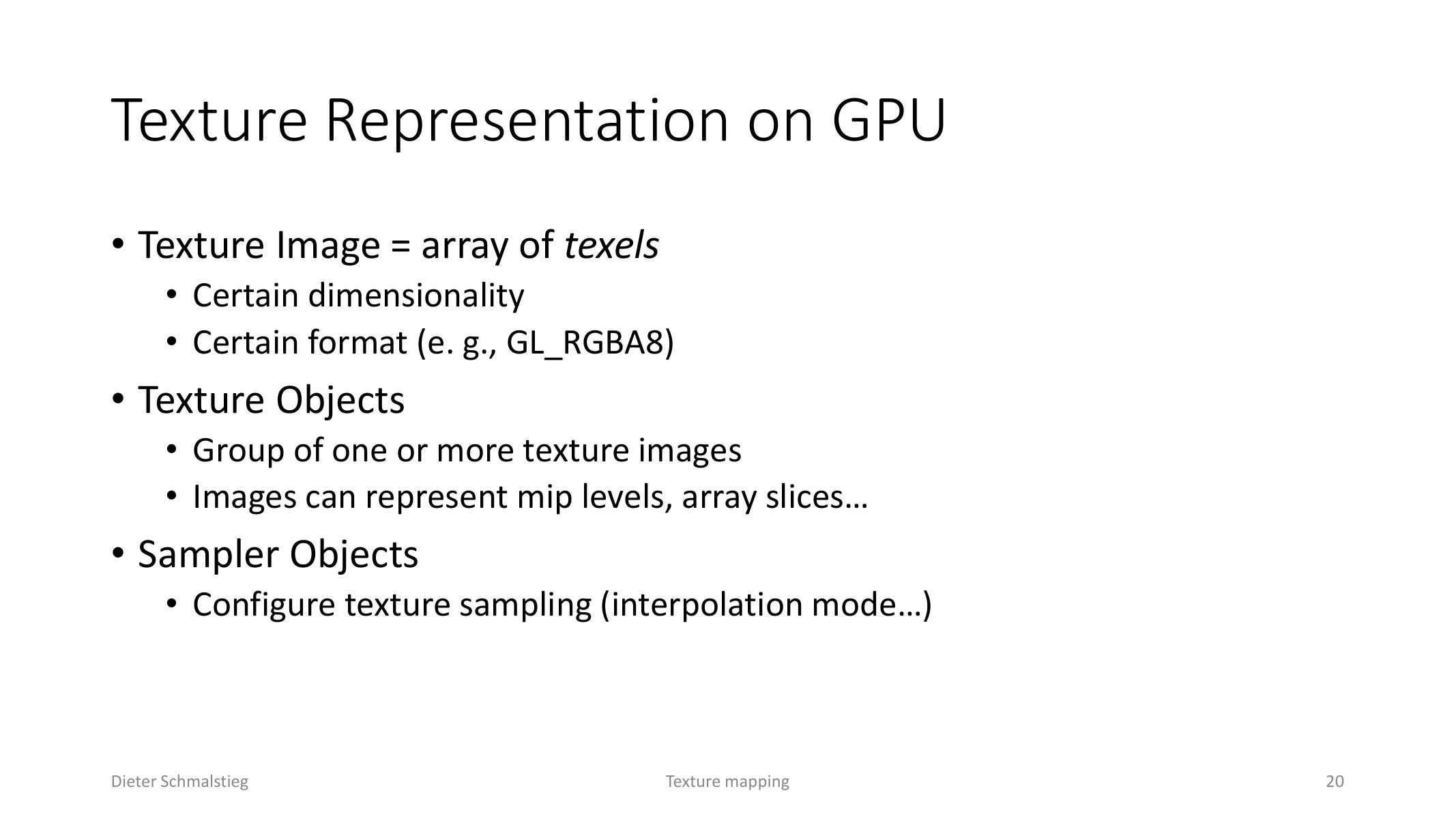
L06_Pg-20: GPU texture state separates image data from sampling behavior.
On the GPU, a texture image is an array of texels with dimensionality and a format such as GL_RGBA8. A texture object groups one or more images, including mip levels or array slices. A sampler object configures how lookups behave: filtering, address mode, and related sampling state.
A typical shader setup uses:
- a texture object holding the data,
- a sampler object describing interpolation/addressing,
- texture units that bind texture and sampler state,
- a fragment shader sample operation using interpolated UV coordinates.
Basic Fragment Shader
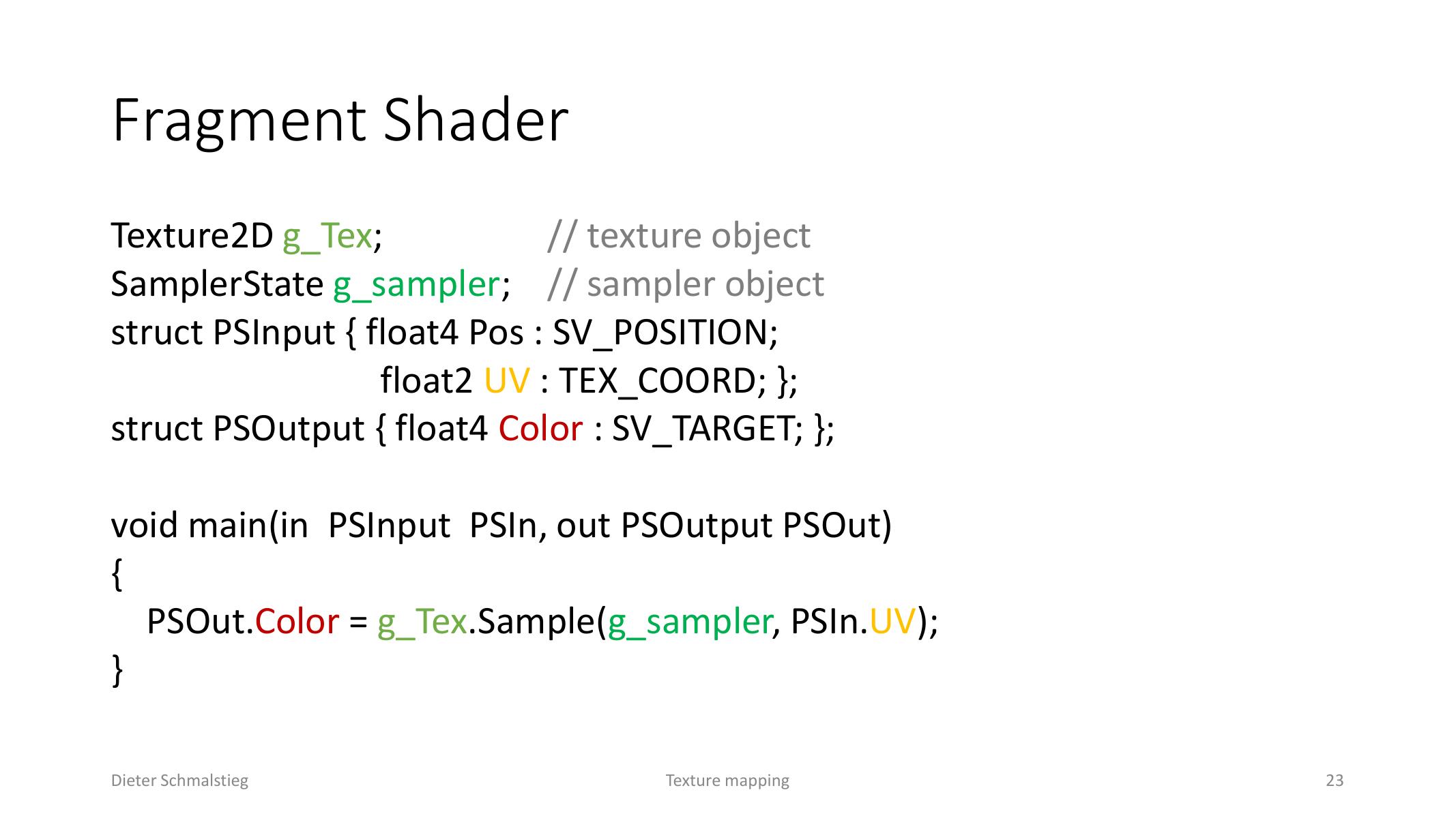
L06_Pg-23: A minimal pixel shader samples a texture object through a sampler using interpolated UV coordinates.
The basic texture shader reads the interpolated UV from the pixel input and samples a texture:
PSOut.Color = g_Tex.Sample(g_sampler, PSIn.UV);This is the simplest form of texture mapping: geometry supplies coordinates, the sampler fetches a value, and the shader writes that value as color.
4. Solid and Volumetric Textures
Solid Texturing
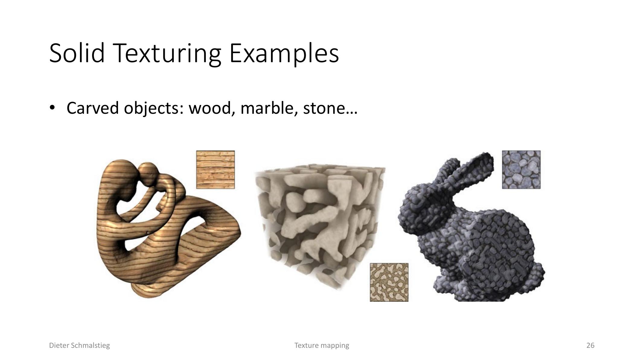
L06_Pg-26: Solid textures make materials appear embedded inside the object volume.
3D texture mapping, often called solid texturing, maps object-space position directly into . This can make materials such as wood, marble, or stone appear to exist inside the object instead of being pasted onto the surface.
Procedural solid textures evaluate functions in 3D. For example, regions of can select rings of different colors to create a wood-like material.
Volumetric Textures
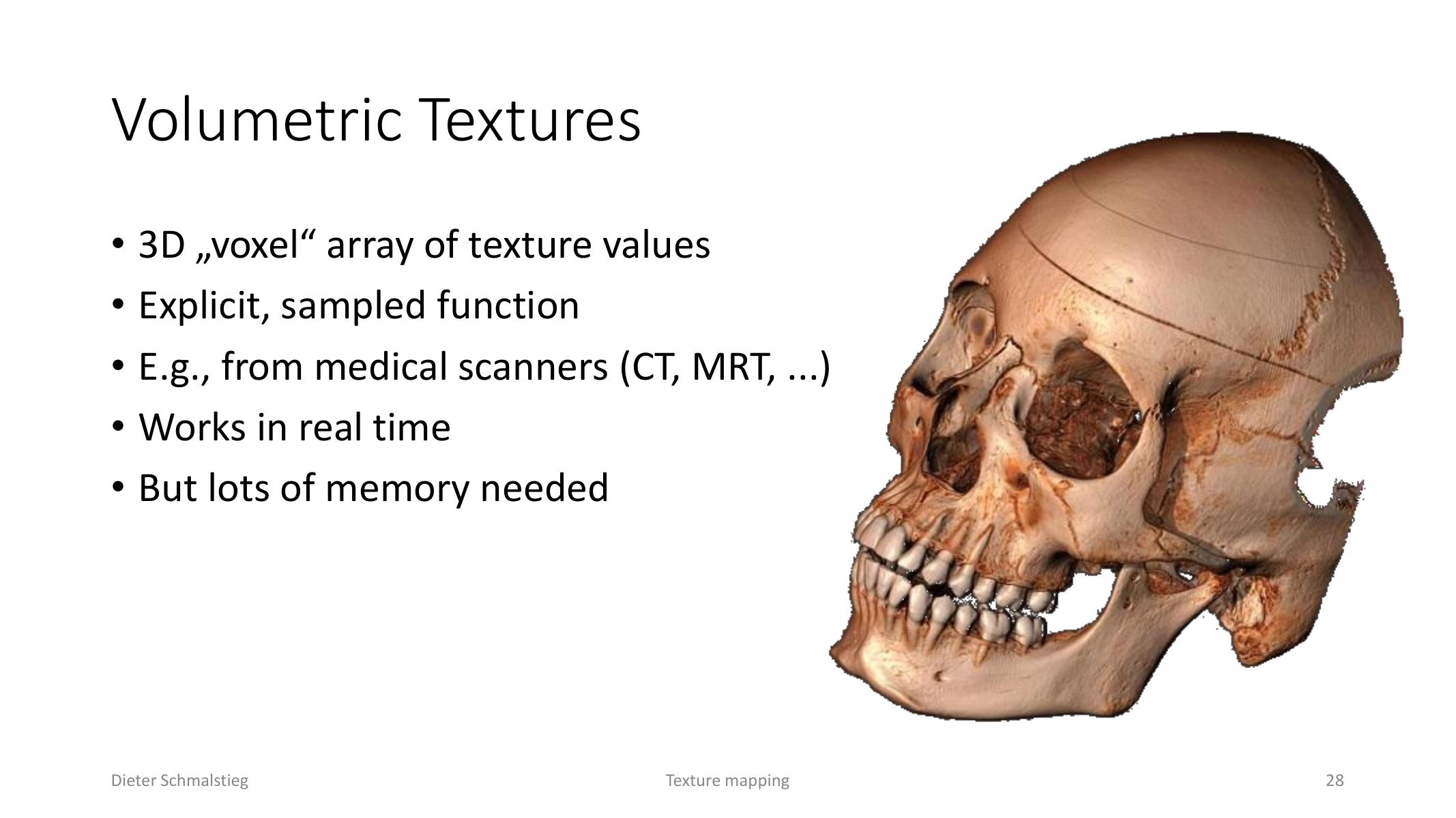
L06_Pg-28: Volumetric textures store sampled voxel data, such as medical scan volumes.
Volumetric textures store an explicit voxel array. They can represent measured data from CT or MRI scanners and can run in real time, but they require much more memory than surface textures.
5. Aliasing, Mip Maps, and Filtering
Texture Aliasing
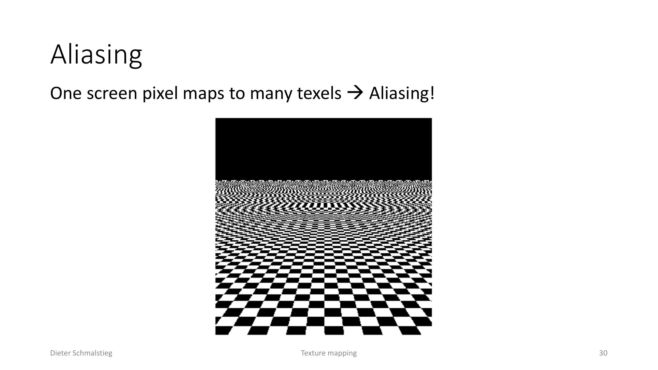
L06_Pg-30: Aliasing occurs when one screen pixel covers many texture samples.
Aliasing appears when one screen pixel maps to many texels. A single nearest lookup ignores most of the covered texels, so high-frequency texture detail becomes flicker, shimmer, or jagged patterns.
The correct pixel value is a weighted average over the pixel footprint projected back into texture space. Real-time rendering approximates that average.
Direct Convolution and Prefiltering
Direct convolution calculates a weighted mean from relevant texels. It is accurate in spirit but expensive if the footprint is large. Prefiltering stores lower-resolution versions of the texture so the renderer can sample a pre-averaged image.
Mip Mapping
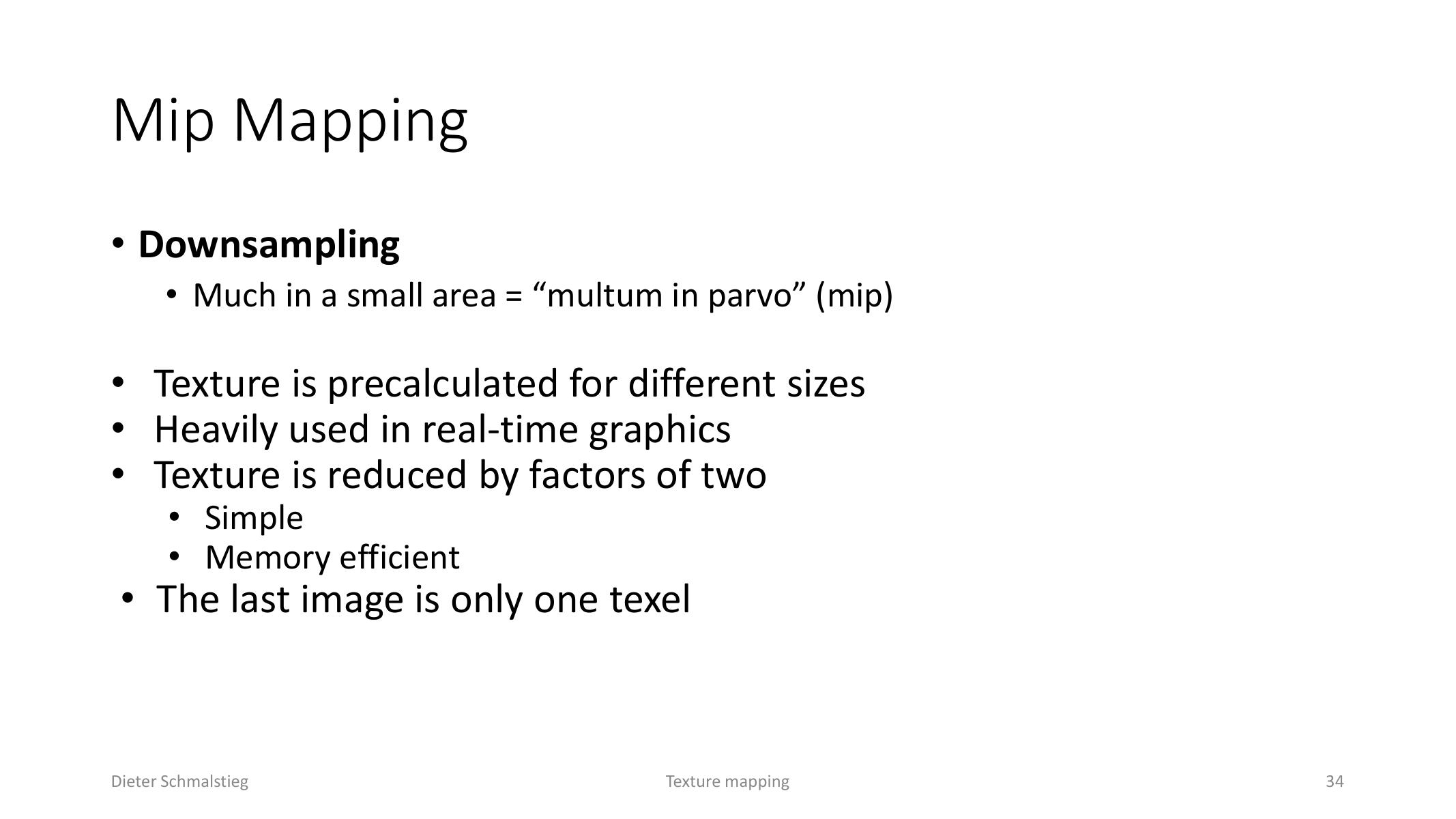
L06_Pg-34: Mip mapping stores prefiltered texture levels reduced by powers of two.
Mip mapping precomputes texture levels reduced by factors of two until only one texel remains. At runtime, the GPU estimates the pixel footprint in texture space, chooses the appropriate mip level, and samples there.
Mip maps reduce bandwidth and suppress scintillating distant texture detail, but they blur uniformly in all directions.
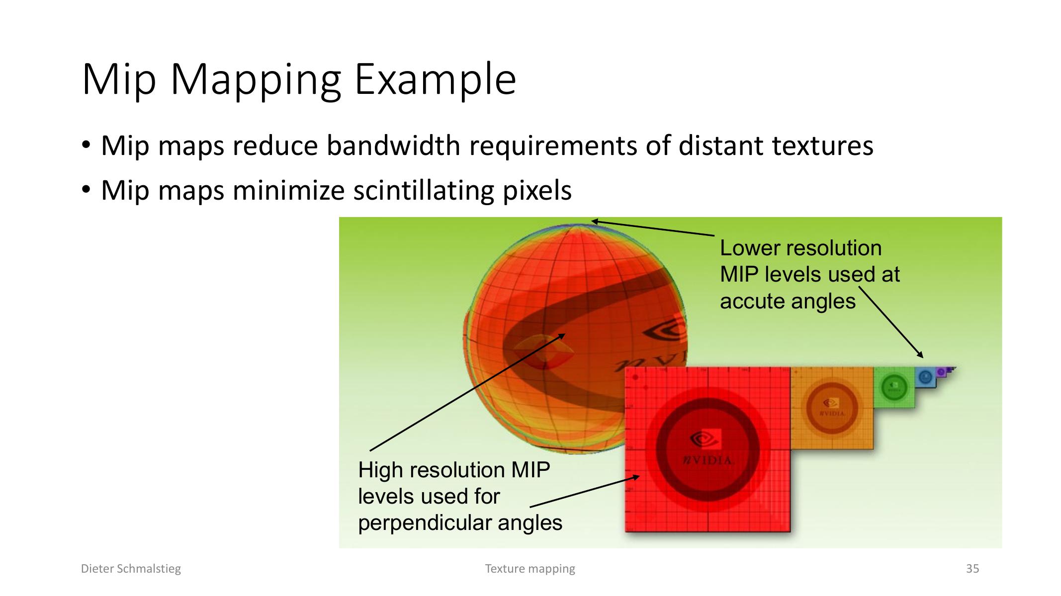
L06_Pg-35: Distant and grazing surfaces use lower mip levels to reduce shimmer and bandwidth.
Bilinear and Trilinear Filtering
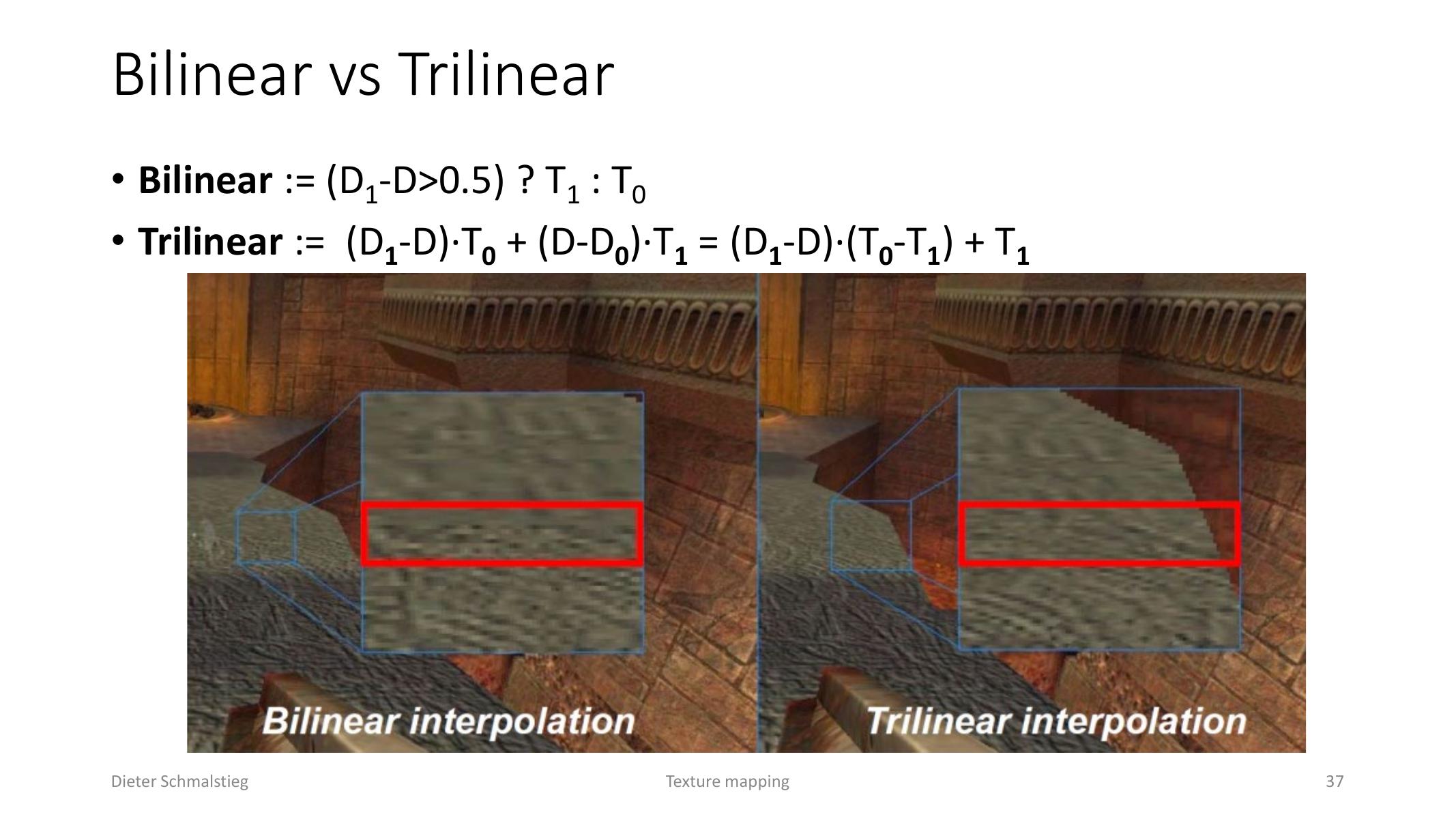
L06_Pg-37: Trilinear filtering blends between two neighboring mip levels instead of snapping to one.
For minification, the renderer chooses between mip levels:
- Bilinear mip selection chooses one mip level and bilinearly samples texels inside it.
- Trilinear filtering bilinearly samples two neighboring mip levels and interpolates between the two results.
For magnification, where the highest-resolution level is still too small, bilinear upsampling reconstructs a value from four neighboring texels according to distance in .
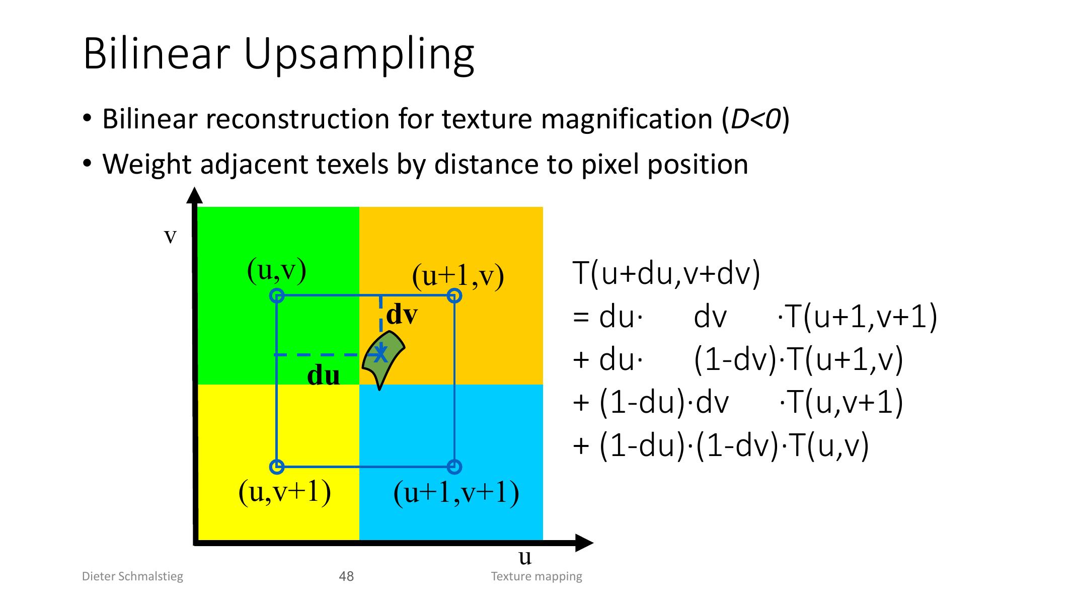
L06_Pg-48: Bilinear reconstruction weights four neighboring texels according to the sample position.
Anisotropic Filtering
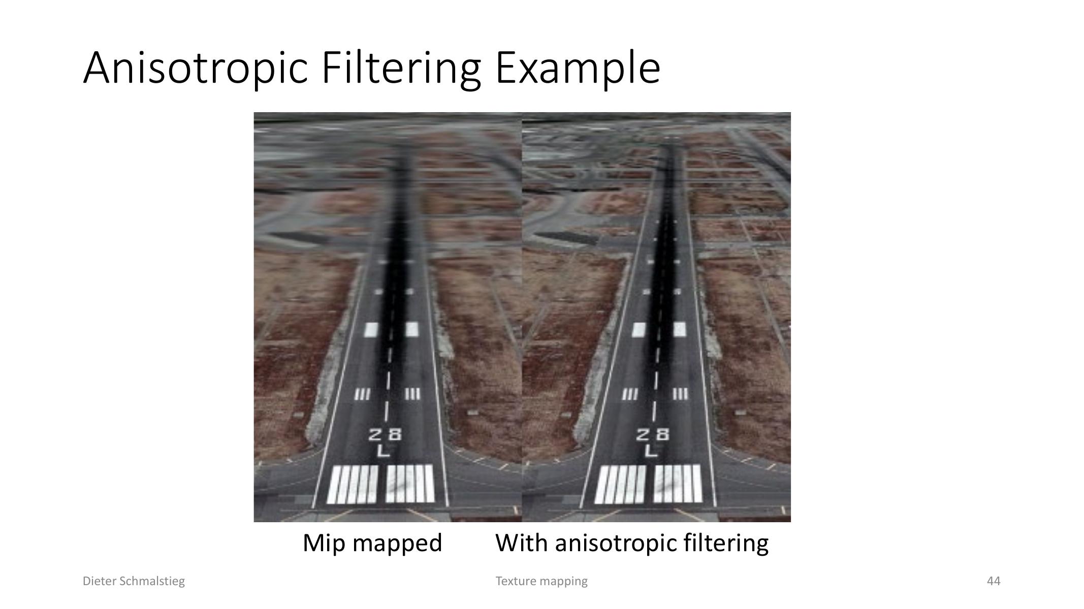
L06_Pg-44: Anisotropic filtering preserves detail at oblique viewing angles better than isotropic mip mapping.
Mip mapping assumes the footprint is roughly square. At oblique viewing angles, the projected footprint becomes stretched, so isotropic mip mapping over-blurs. Anisotropic filtering samples along the major axis of the footprint and uses multiple trilinear samples to preserve detail.
Rip mapping extends mip mapping with anisotropic prefiltering, but it needs much more memory.
6. Multipass Rendering, Blending, and Multitexturing
Multipass Rendering
Real-time effects often exceed what a single local lighting pass can express. Multipass rendering builds effects by rendering auxiliary results and feeding them into later passes.
Two common methods are:
- render to an auxiliary buffer and use it later as a texture,
- redraw the scene while combining fragments through framebuffer operations.
Render to Texture
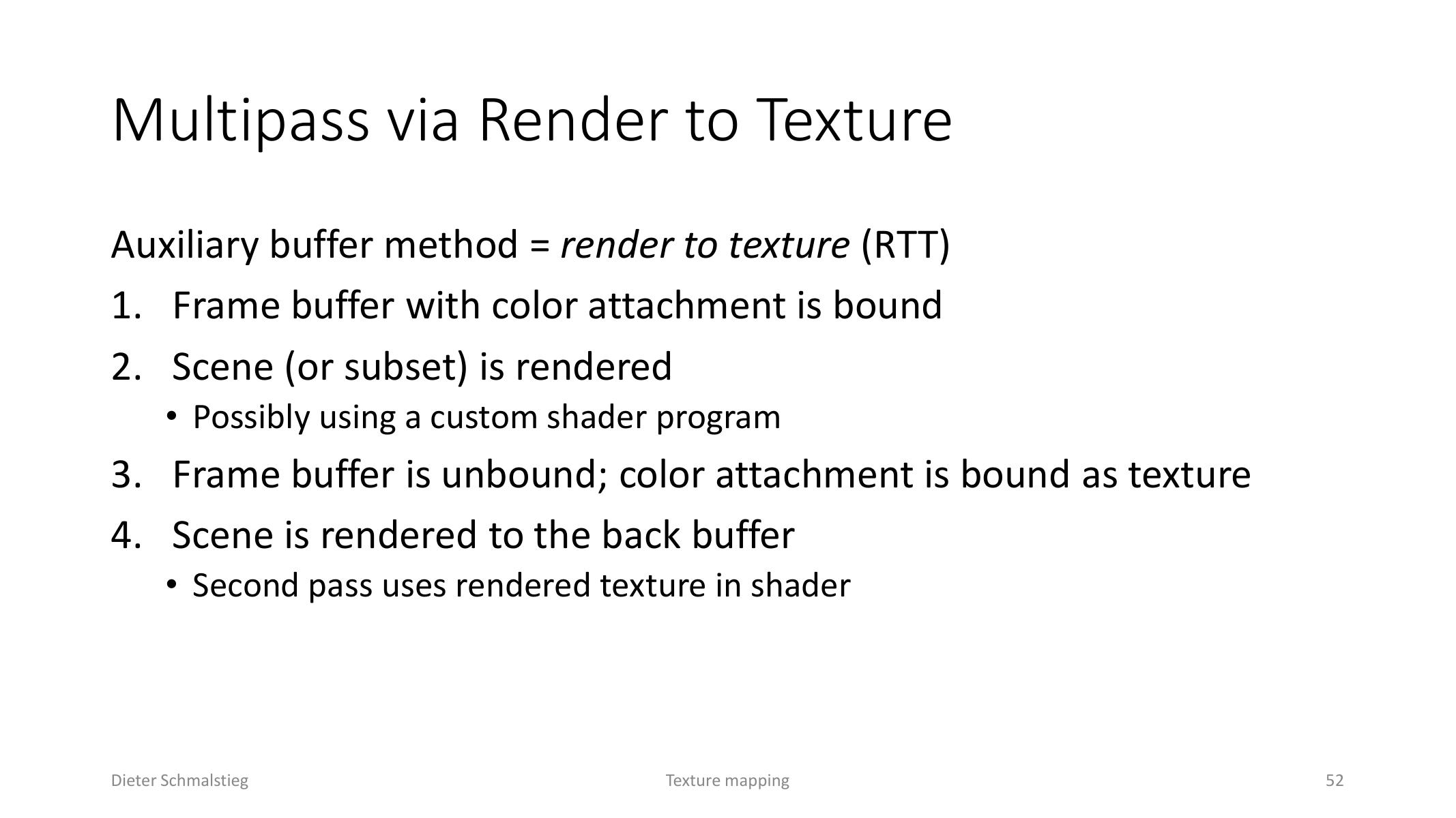
L06_Pg-52: Render-to-texture writes an auxiliary pass into a texture and samples it in a later pass.
Render-to-texture binds a framebuffer with a color attachment, renders a scene or subset into that attachment, unbinds the framebuffer, then samples the result in a later pass. Environment maps, shadow maps, reflections, and post-processing all use this pattern.
Framebuffer Blending
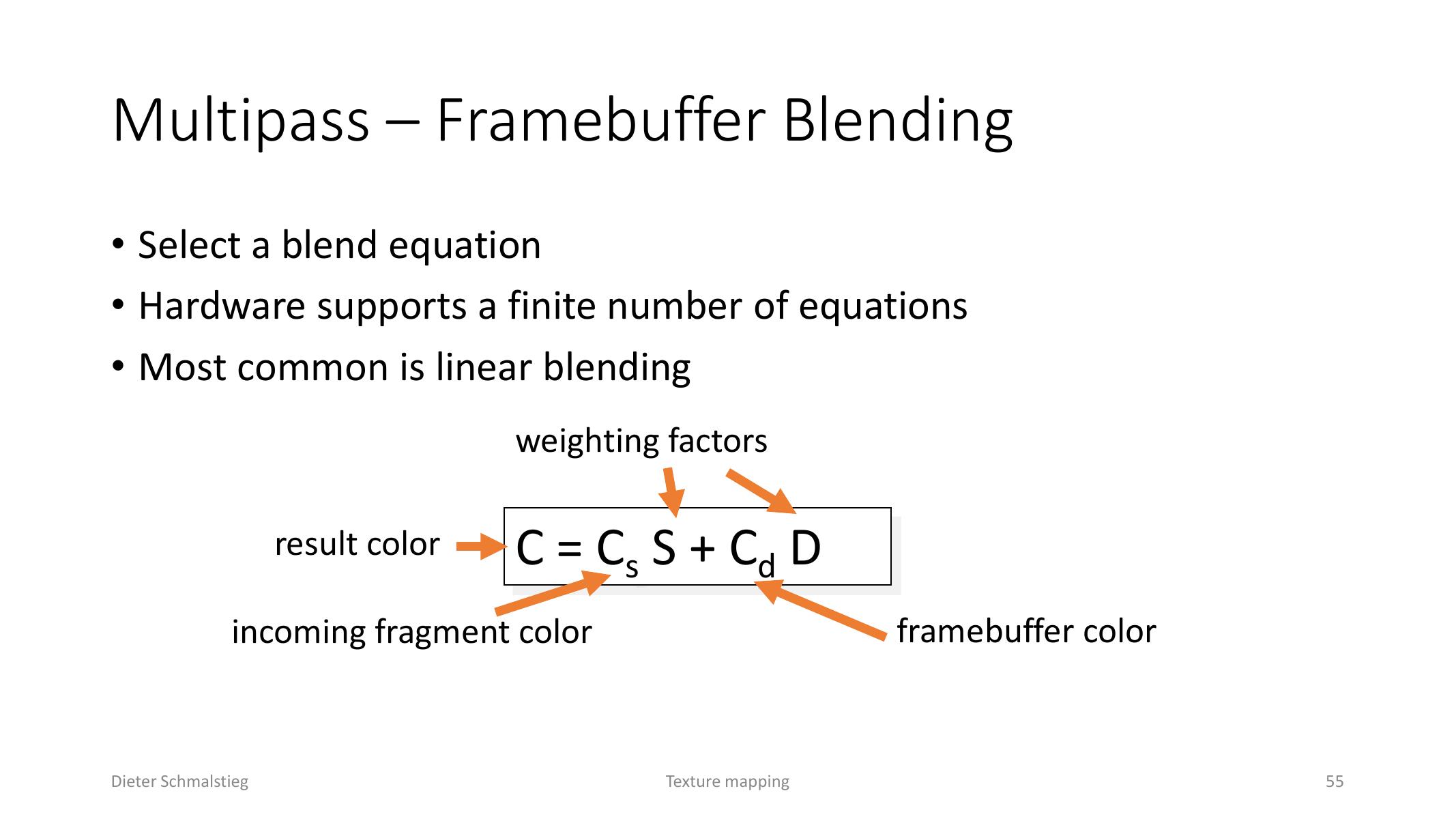
L06_Pg-55: Linear blending combines incoming fragment color with the destination framebuffer color.
Blending combines the incoming fragment color with the destination color already stored in the framebuffer:
Here is the source fragment, is the destination framebuffer color, and are selected blend factors. Standard transparency uses:
Alpha enables translucent surfaces, compositing, and antialiasing, but partially transparent objects usually need depth sorting because the z-buffer alone cannot correctly order fractional opacity.
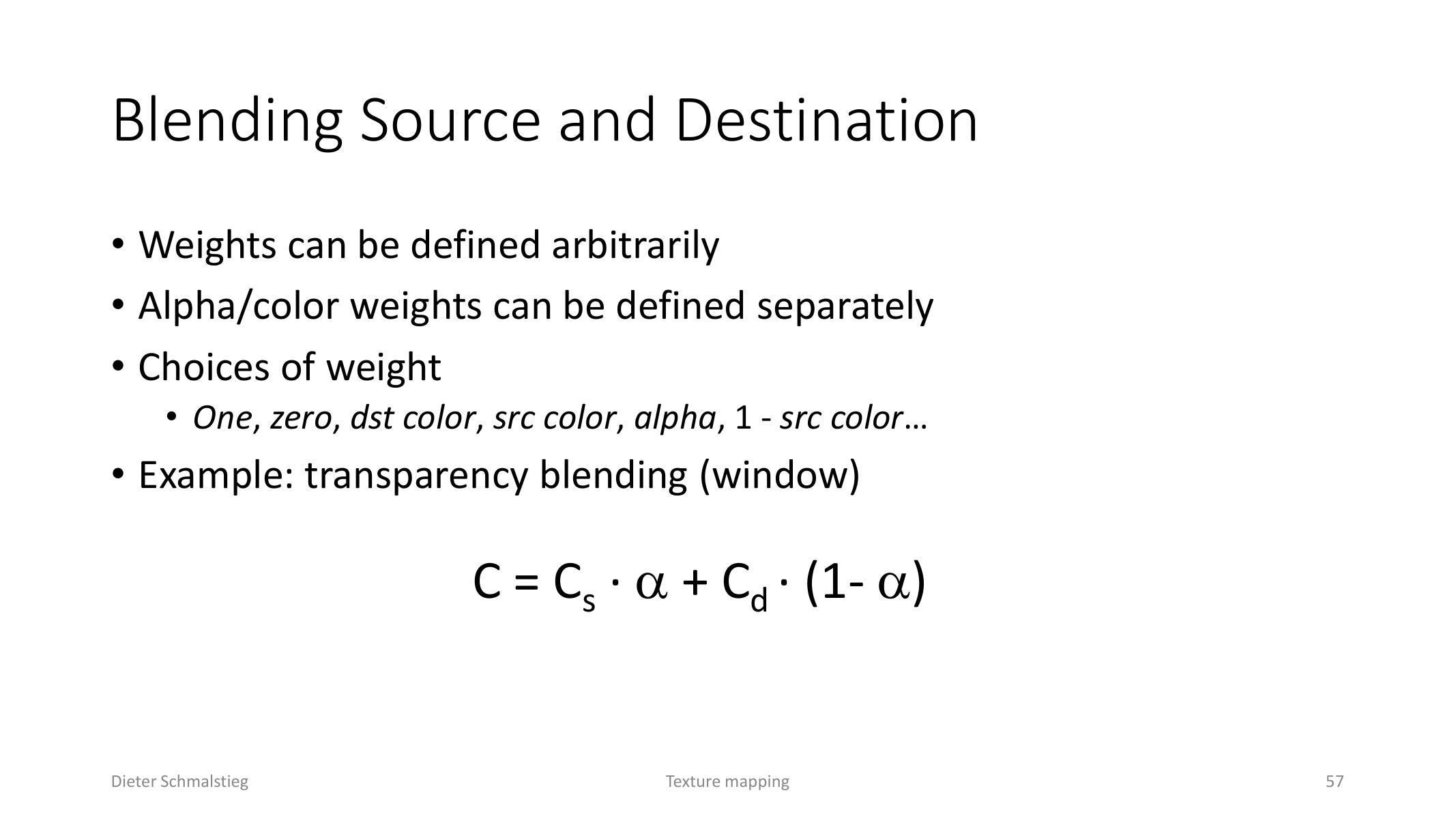
L06_Pg-57: Common transparency blending weights the source by alpha and the destination by one minus alpha.
Multitexturing
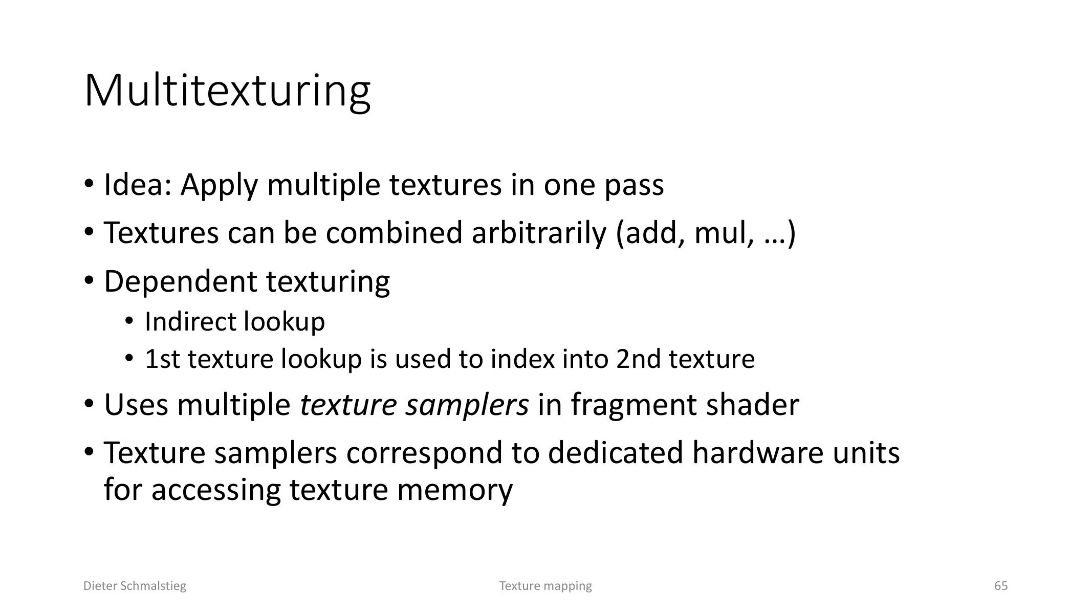
L06_Pg-65: Multitexturing combines several texture lookups in one shader pass.
Multitexturing applies multiple textures in one pass. A shader can combine a base material, decal, opacity map, light map, gloss map, or other data sources with arbitrary arithmetic.
Dependent texturing uses the result of one texture lookup as coordinates for another lookup.
Light Mapping
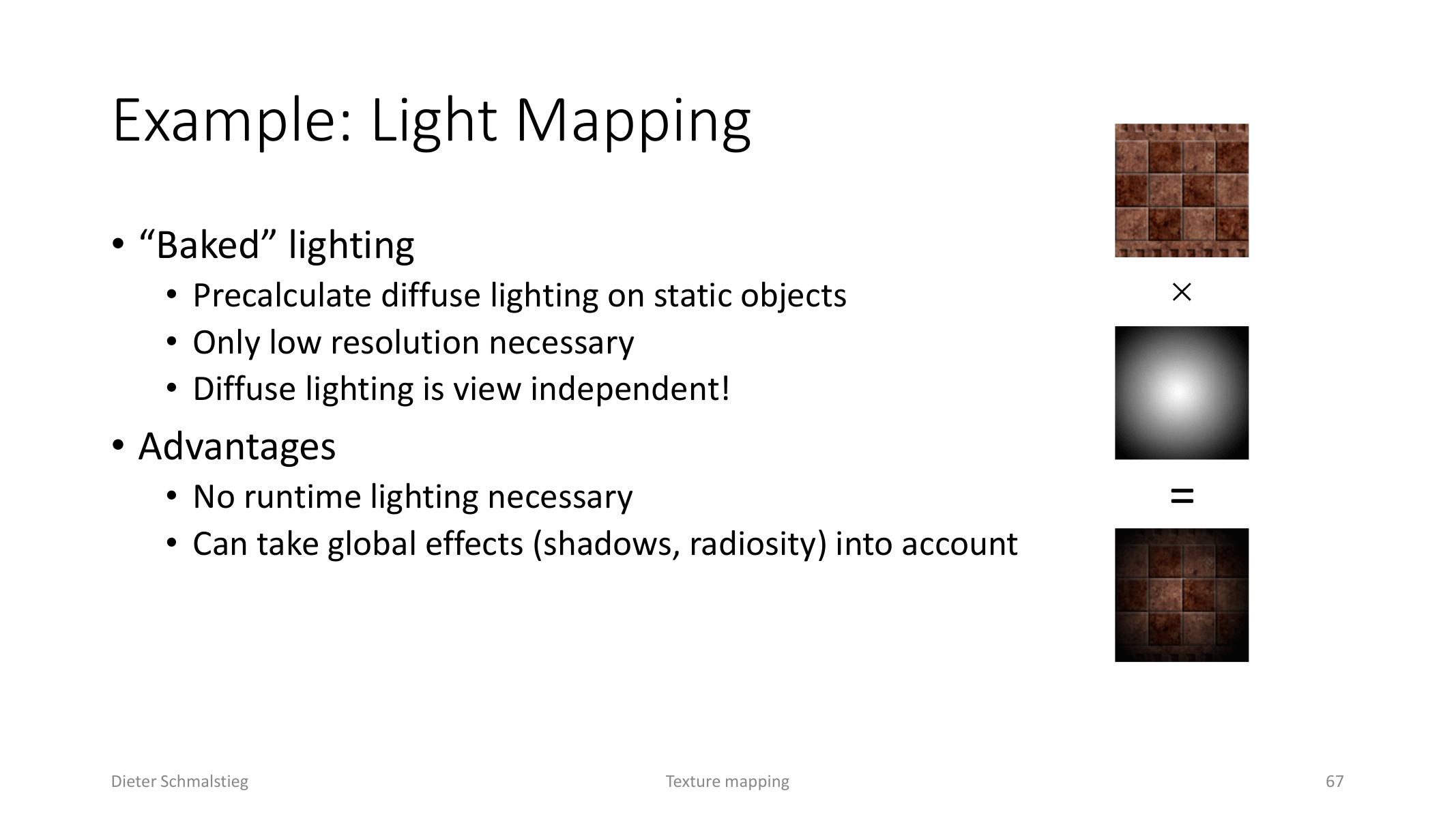
L06_Pg-67: A light map stores baked view-independent diffuse lighting for static surfaces.
Light maps bake diffuse lighting for static objects. Because diffuse lighting is view-independent, it can be stored at low resolution and multiplied with tiled surface textures at runtime. This avoids expensive dynamic lighting but cannot represent dynamic changes unless the maps are recomputed or supplemented.
7. Projective and Environment Mapping
Projective Texture Mapping
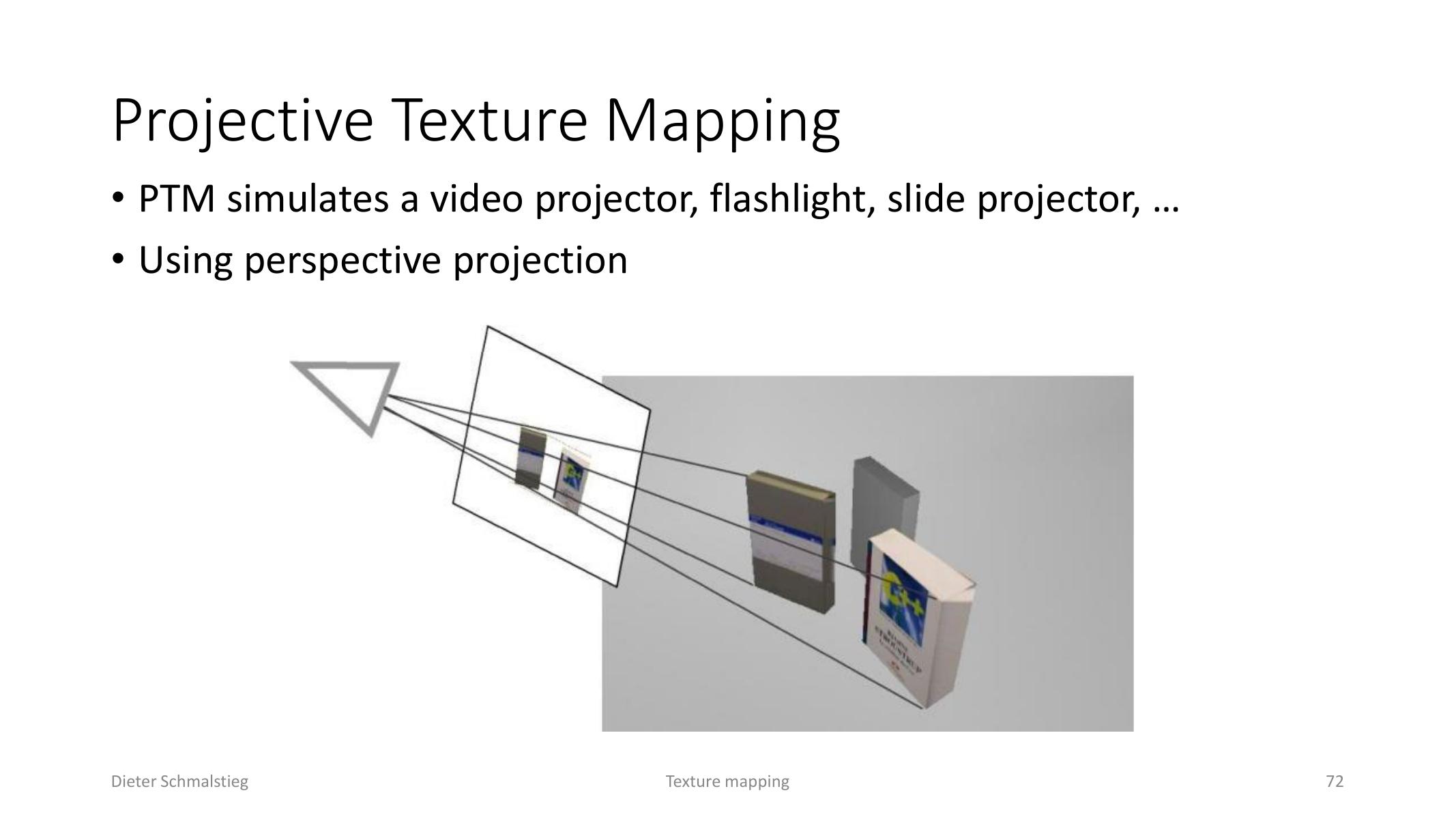
L06_Pg-72: Projective texture mapping treats the texture like a projector or flashlight.
Projective texture mapping simulates a projector, flashlight, or depth camera by mapping object coordinates into a light or projector frustum. The transformation is projective, usually represented by a matrix.
Environment Mapping
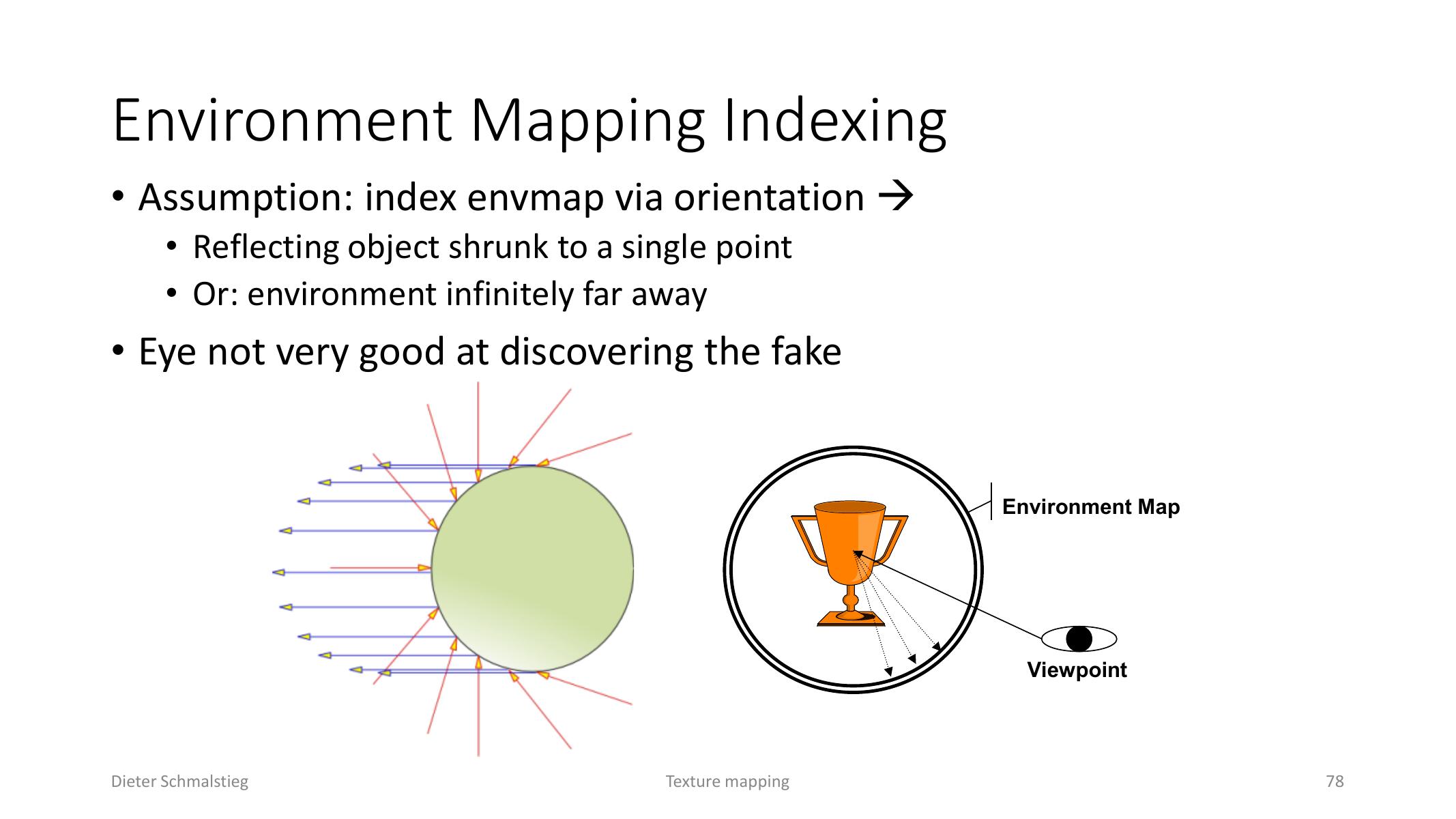
L06_Pg-78: Environment maps approximate reflection by indexing the environment with orientation.
Environment mapping uses a texture to fake reflections. The key approximation is that the reflecting object is treated as a single point or that the environment is infinitely far away. This is often convincing enough because the eye is tolerant of that simplification.
Common environment map layouts include sphere maps, cube maps, and dual paraboloid maps. Cube maps are dominant in real-time rendering because they have low distortion and hardware support.
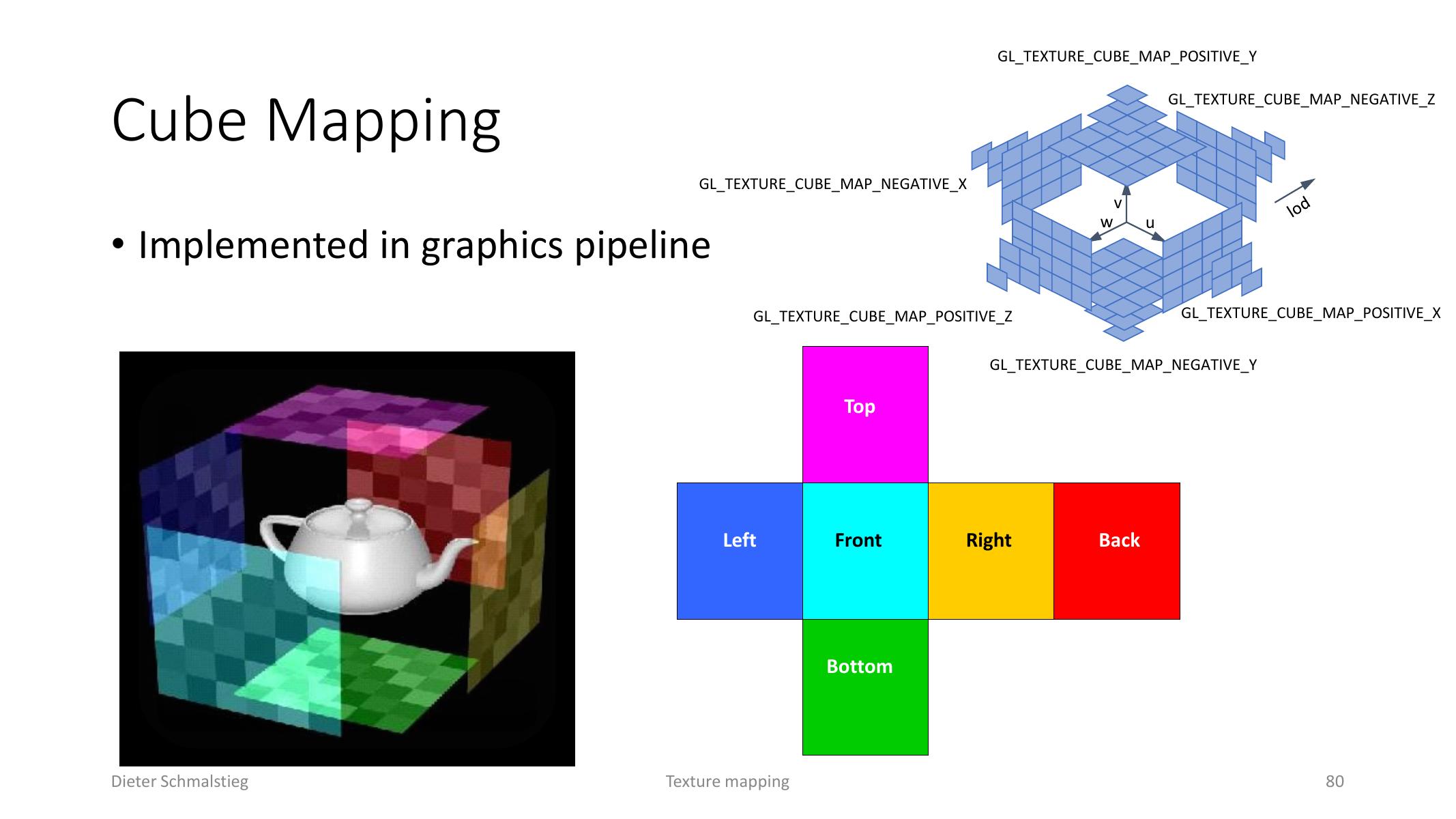
L06_Pg-80: Cube maps store six square faces and are sampled by a 3D direction.
Cube Map Addressing
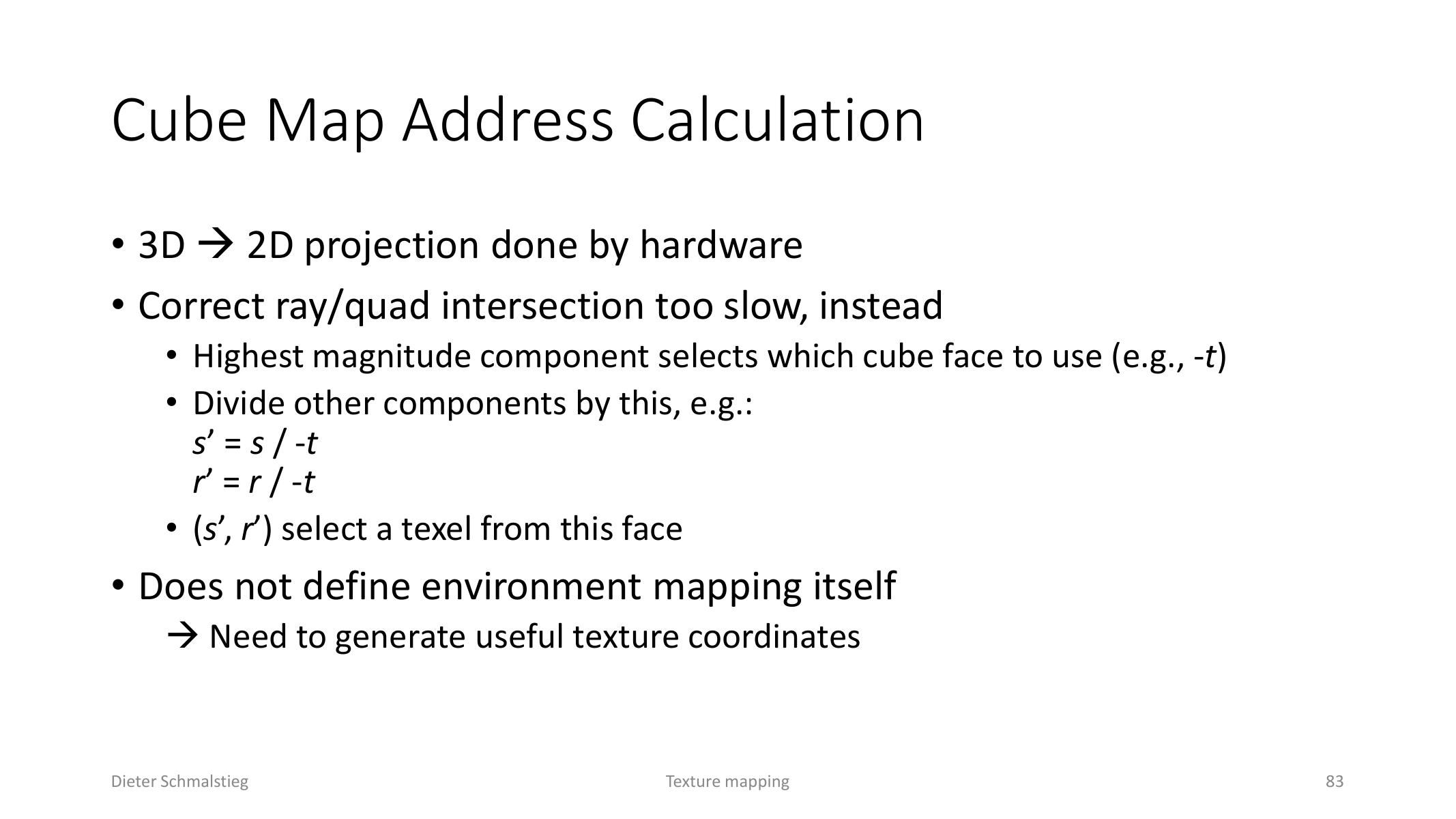
L06_Pg-83: Hardware chooses the cube face by the largest direction component and projects the other two components.
A cube map is sampled with a 3D direction vector. Hardware selects the cube face using the largest-magnitude vector component, projects the other two components onto that face, and fetches the texel.
The reflection vector comes from the usual law of reflection:
The important practical detail is coordinate space: the reflection vector must be in the same space as the cube map.
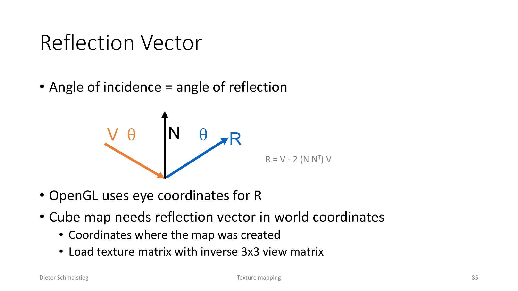
L06_Pg-85: The reflection vector must be expressed in the coordinate system where the cube map was created.
8. Per-Pixel Lighting and Bump Mapping
Per-Pixel Lighting
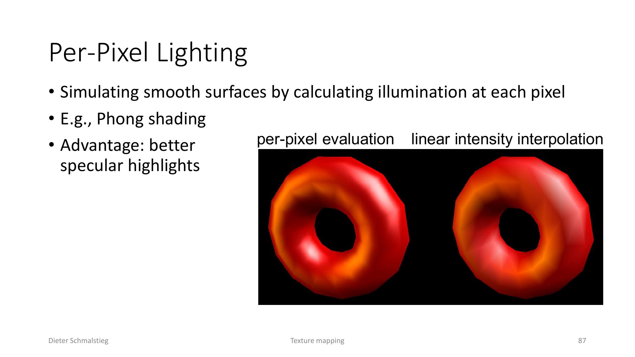
L06_Pg-87: Per-pixel lighting evaluates illumination at each fragment for better highlights.
Per-pixel lighting evaluates illumination in the fragment shader instead of interpolating final color from vertices. The rasterizer interpolates normals or other vectors, and the fragment shader renormalizes and shades each pixel. This gives much better specular highlights.
Bump Mapping
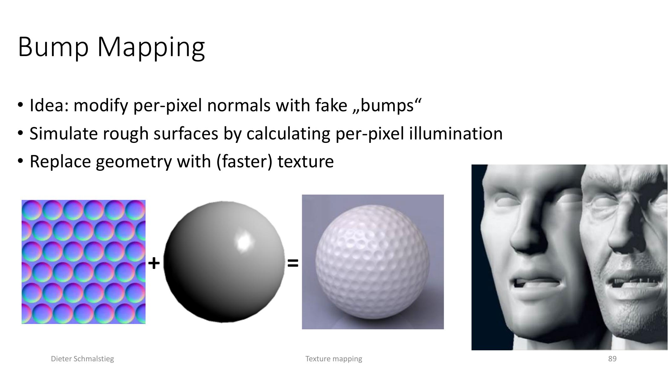
L06_Pg-89: Bump mapping replaces geometric surface relief with per-pixel normal changes.
Bump mapping modifies per-pixel normals to fake small surface relief. The geometry remains unchanged, but lighting reacts as if the surface had fine bumps.
A height field offsets a base surface :
The changed partial derivatives imply a perturbed normal. In real-time rendering, the derivative math is usually precomputed or encoded into a map.
Normal Maps
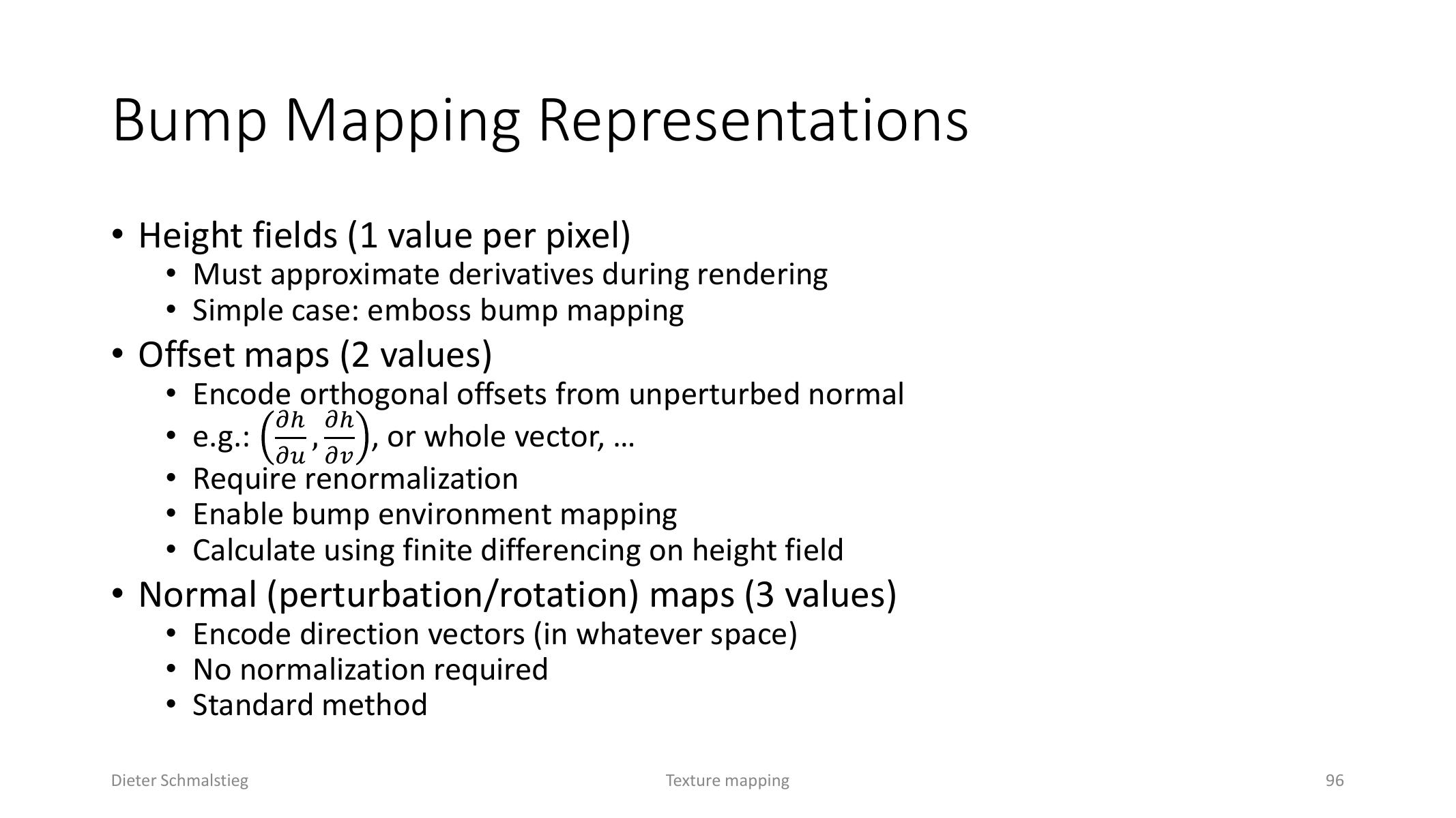
L06_Pg-96: Normal maps store a direction per texel and are the standard representation for real-time bump detail.
Bump data can be represented as:
- height fields with one value per pixel,
- offset maps with two derivative-like values,
- normal maps with three direction components.
Normal maps are the standard method because the shader can directly fetch a perturbed normal direction.
Tangent Space
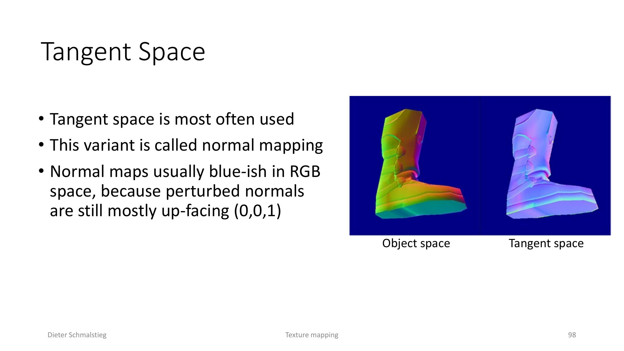
L06_Pg-98: Tangent-space normal maps are blue because most normals still point close to the local +z direction.
Normal maps are usually stored in tangent space. Each vertex needs a tangent, bitangent, and normal frame. In this space the unperturbed surface normal is approximately , which is why normal maps are usually blue.
The fragment shader transforms light and view vectors into tangent space or transforms the sampled normal back into world space before shading.
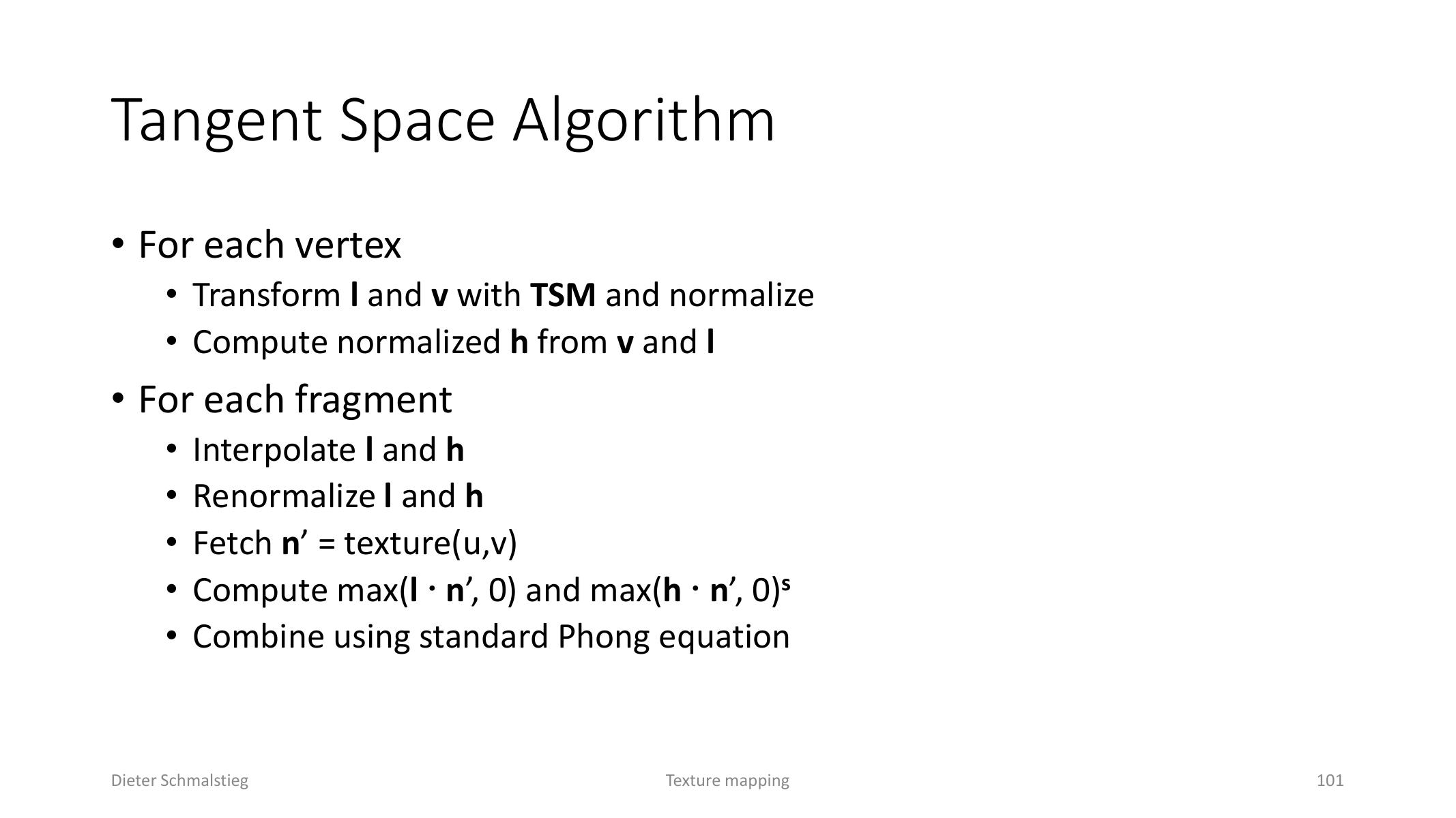
L06_Pg-101: A tangent-space shader fetches the perturbed normal, renormalizes vectors, and applies the lighting equation.
Reflective Bump Mapping
Environment map bump mapping combines normal mapping with cube map lookup. The shader samples a perturbed normal, computes a reflection vector using that normal, and uses the result to sample the cube map. This is a dependent texture lookup.
9. Beyond Bump Mapping
Bump Mapping Limits
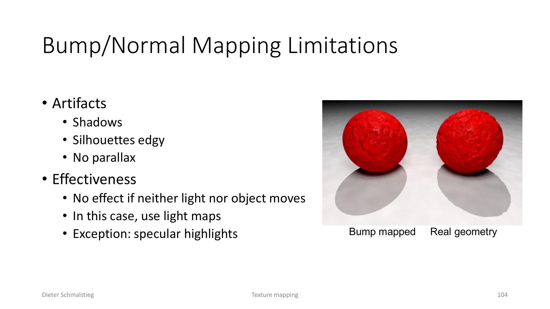
L06_Pg-104: Bump mapping changes lighting but not silhouettes, shadows, or true surface parallax.
Bump mapping changes lighting but not geometry. It cannot fix silhouettes, true shadows, or parallax by itself. If neither the light nor the object moves, the effect may disappear except for specular highlights.
Displacement Mapping
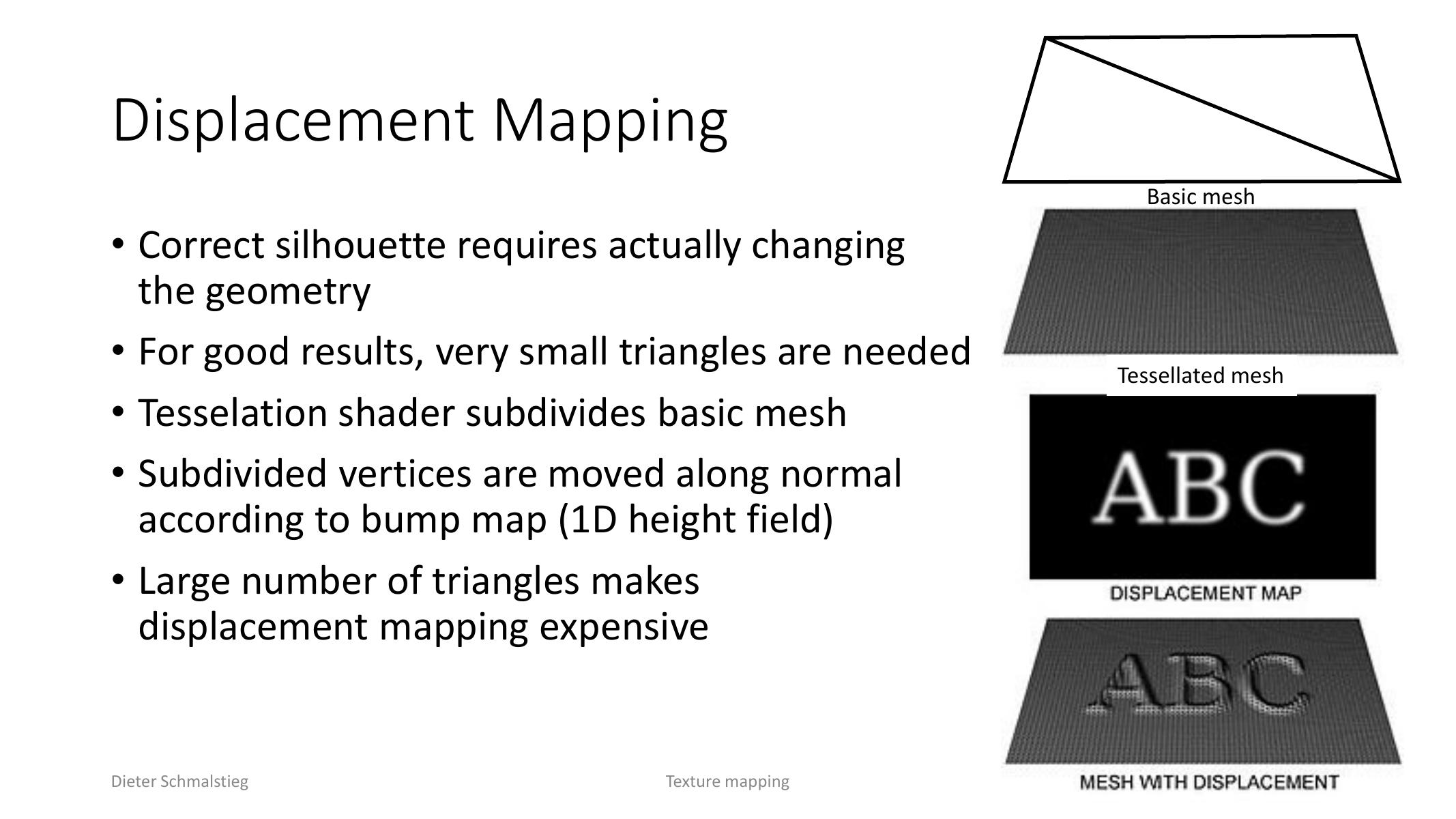
L06_Pg-105: Displacement mapping changes geometry after tessellation to recover real silhouettes.
Displacement mapping actually changes geometry by subdividing a mesh and moving vertices along the normal using a height field. It can produce correct silhouettes, but it needs many small triangles and is expensive.
Parallax Mapping
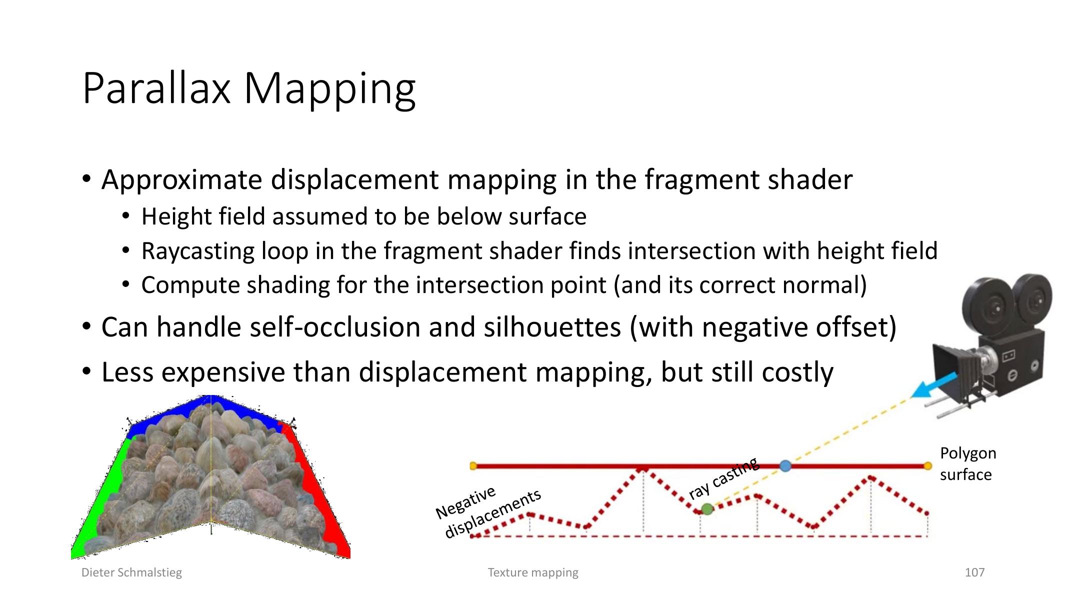
L06_Pg-107: Parallax mapping raycasts a height field in the fragment shader to approximate displaced depth.
Parallax mapping approximates displacement inside the fragment shader. It treats the height field as lying below the surface and raycasts in texture space to find an apparent intersection. It can handle self-occlusion and richer depth cues than bump mapping, but the raycasting loop is still costly.
Parallax occlusion mapping improves the intersection by interpolating between sampled height values.
10. Diligent Engine Texture Pipeline
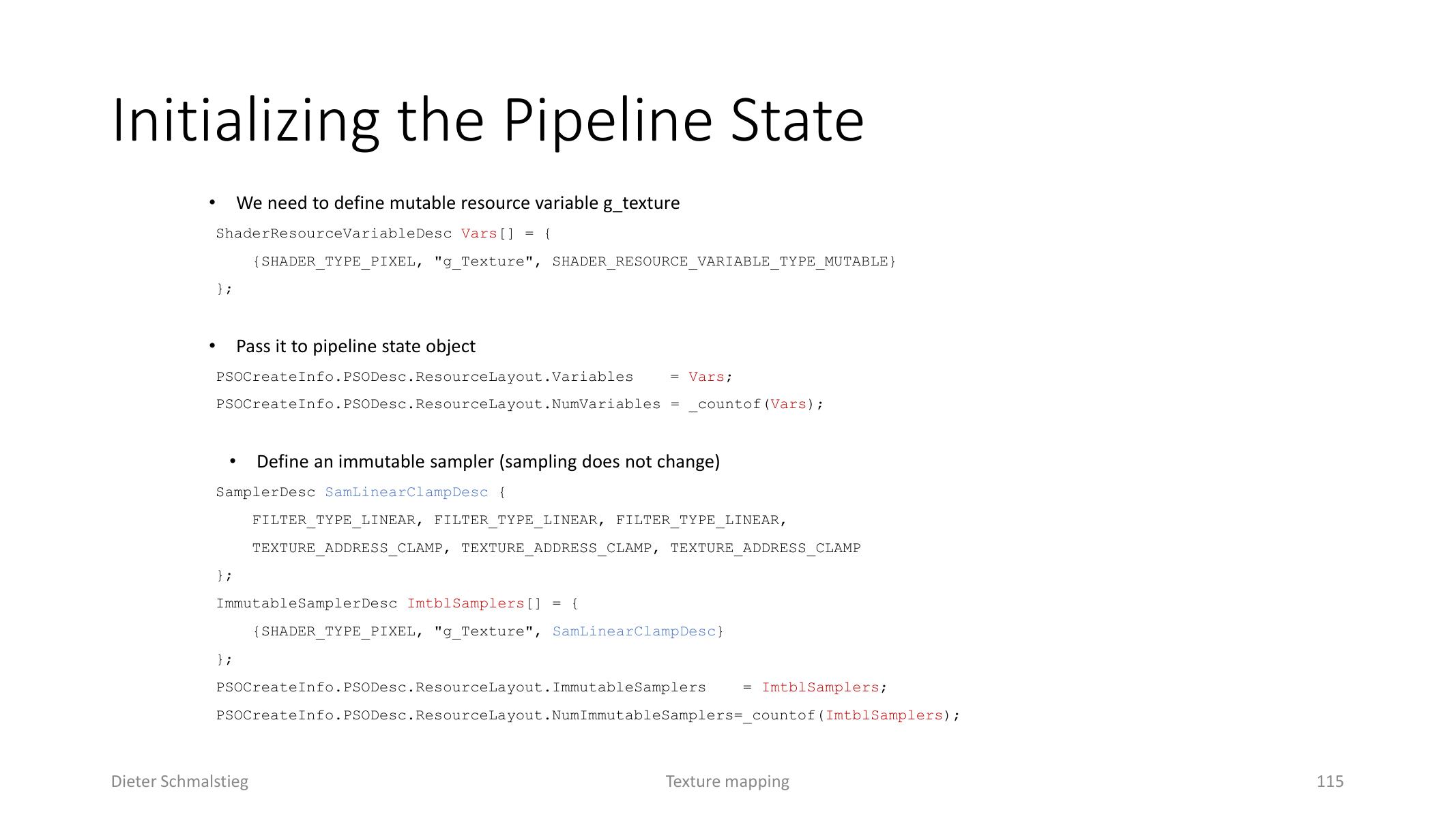
L06_Pg-115: The pipeline state declares the mutable texture variable and an immutable sampler.
The lecture closes with the Diligent Engine texture example. The data flow is:
- the vertex shader passes UV coordinates to the pixel shader,
- the pixel shader samples
g_Texthroughg_sampler, - the pipeline state declares a mutable texture resource variable,
- an immutable sampler defines linear clamp sampling,
- the texture is loaded from file and exposed as a shader resource view,
- the shader resource binding commits the texture before the indexed draw call.
The conceptual point is the same as the first texture shader: vertices carry coordinates, the sampler controls lookup, and the fragment/pixel shader decides how to use the fetched value.
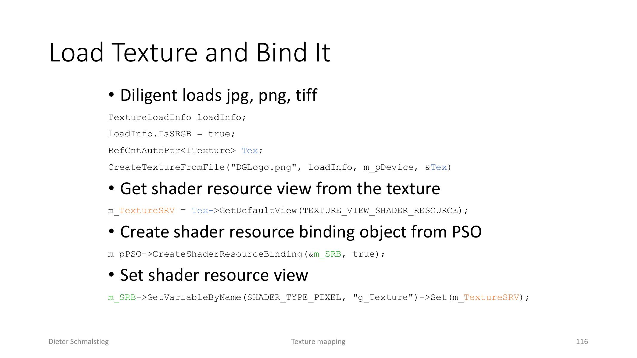
L06_Pg-116: The texture file is loaded, converted to a shader resource view, and bound before drawing.
Applied Exam Focus
- Texture definition: a texture is a per-fragment lookup function, not just a color image.
- Parametrization: know planar, cylindrical/spherical, box, and manual unwrapping tradeoffs.
- Addressing modes: border/static color, clamp, repeat, mirror.
- Texture objects vs samplers: data and sampling state are separate concepts.
- Aliasing: happens when one pixel covers many texels; mip maps prefilter lower-resolution versions.
- Filtering: bilinear interpolates within one level; trilinear interpolates between mip levels; anisotropic filtering handles stretched footprints.
- Multipass rendering: render-to-texture and framebuffer blending are the two core mechanisms.
- Blending: transparency commonly uses and needs ordering care.
- Environment mapping: cube maps use direction vectors and reflection vectors in the correct coordinate space.
- Bump vs displacement vs parallax: bump/normal maps change lighting only, displacement changes geometry, parallax raycasts a height field in the fragment shader.
Self-Check
- What is texture aliasing, and how does mip mapping address it?
Answer
Aliasing happens when a single screen pixel covers many texels. A single nearest sample ignores most of those texels, so high-frequency texture content turns into shimmer or jagged patterns. Mip mapping precomputes prefiltered lower-resolution versions of the texture and samples whichever level matches the pixel footprint, so the sample already represents an average over the covered texels.
- What is the difference between bilinear, trilinear, and anisotropic filtering?
Answer
Bilinear samples four neighboring texels inside a chosen mip level and blends by sub-texel position. Trilinear takes bilinear samples on two neighboring mip levels and blends between them, smoothing the transition between mips. Anisotropic filtering recognizes that the footprint is often elongated at oblique angles and takes multiple trilinear samples along the long axis, preserving detail that isotropic mipping would over-blur.
- Write the standard transparency blend equation and explain why transparent objects still need sorting.
Answer
. The result depends on the destination color already in the framebuffer, so the blend is order-dependent. Two overlapping transparent fragments drawn in different orders give different final colors, so transparent surfaces are typically sorted back-to-front (or use order-independent transparency techniques) to look correct.
- Why are tangent-space normal maps mostly blue?
Answer
Tangent space orients each fragment so the unperturbed surface normal points along . The normal-map texel encodes the perturbed normal as remapped to , so a close to becomes nearly full blue. Real surface bumps deviate only slightly from , so almost every pixel is mostly blue with smaller red and green components for the lateral tilt.
- Compare bump/normal mapping, displacement mapping, and parallax mapping in terms of geometry vs lighting.
Answer
Bump and normal mapping only change per-fragment shading: the lighting reacts as if the surface had bumps, but silhouettes and self-shadowing stay flat. Displacement mapping actually moves geometry along the normal after tessellation, producing real silhouettes and shadows at the cost of many small triangles. Parallax mapping raycasts a height field in the fragment shader to fake an offset texture lookup, giving better depth cues than bumps but still no real geometry.
- What are the standard texture addressing modes, and when is each appropriate?
Answer
Clamp (or clamp-to-edge) returns the edge texel for out-of-range coordinates - useful for textures with a meaningful border like a sprite. Repeat (or wrap) tiles the texture infinitely, ideal for periodic patterns like floor tiles or grass. Mirror reflects on each repeat, which hides the visible seam between tiles. Border (or clamp-to-border) returns a fixed border colour for out-of-range coordinates, useful for masks or single-instance decals where you want surrounding pixels to be a known colour rather than a stretched edge.
- Why is the texture object separate from the sampler in modern APIs, and what does that decoupling enable?
Answer
A texture object describes the data: pixel values, format, mip levels. A sampler describes how to read that data: filter mode (nearest/bilinear/trilinear), addressing mode, anisotropy, comparison function. Separating them lets one sampler be reused across many textures (one immutable “linear-clamp anisotropic” sampler shared by all PBR materials, for instance) and lets one texture be sampled with different settings from different shaders (e.g. a shadow-map texture sampled with a depth-comparison sampler in the lighting pass and a regular sampler for debug visualization). This is more efficient than the old GL model where each texture had its own embedded sampling state.
- What is the difference between a cube map and a sphere map for environment mapping, and which is preferred?
Answer
A sphere map flattens the entire environment onto a single 2D texture using a paraboloid-like projection; it is cheap but distorts heavily near the seams and “behind” the camera. A cube map uses six square faces, one per axis direction, sampled with a 3D reflection vector that picks the face and 2D coordinate in hardware; it is uniform in resolution, has no distortion, and is the standard for IBL (image-based lighting) and skyboxes. Modern hardware has native cubemap support, so the cost is the same as a 2D sample. Sphere maps appear mainly in legacy code or as fallback paths.