Previous: (y-06) Computer Vision for AR | AR Index | Next: (y-08) Visual Coherence
Mental Model First
- Tracking gives you a pose, but the pose is only useful if every coordinate system in the system is correctly aligned.
- Calibration is the act of figuring out the static parameters that link those coordinate systems: lens to image, camera to world, eye to display, head to camera.
- Registration is the goal: virtual content must appear in the right place relative to the real world.
- Two coarse categories: camera calibration (internal optics) and display calibration (eye relative to display).
- Even with perfect tracking, error propagation and end-to-end latency still ruin registration if they are not addressed.
The lecture splits calibration into camera calibration and display (to eye) calibration, both serving the goal of registration.
1. Camera Calibration
Camera calibration adjusts internal camera parameters and the nonlinearities introduced by lens distortion.
The intrinsics describe how a 3D ray hitting the sensor maps to a pixel. Lens distortion describes how that mapping deviates from the ideal pinhole model used in the previous lecture. Calibration recovers both so that subsequent computer vision and rendering steps can assume a clean projection.
Lens Distortion
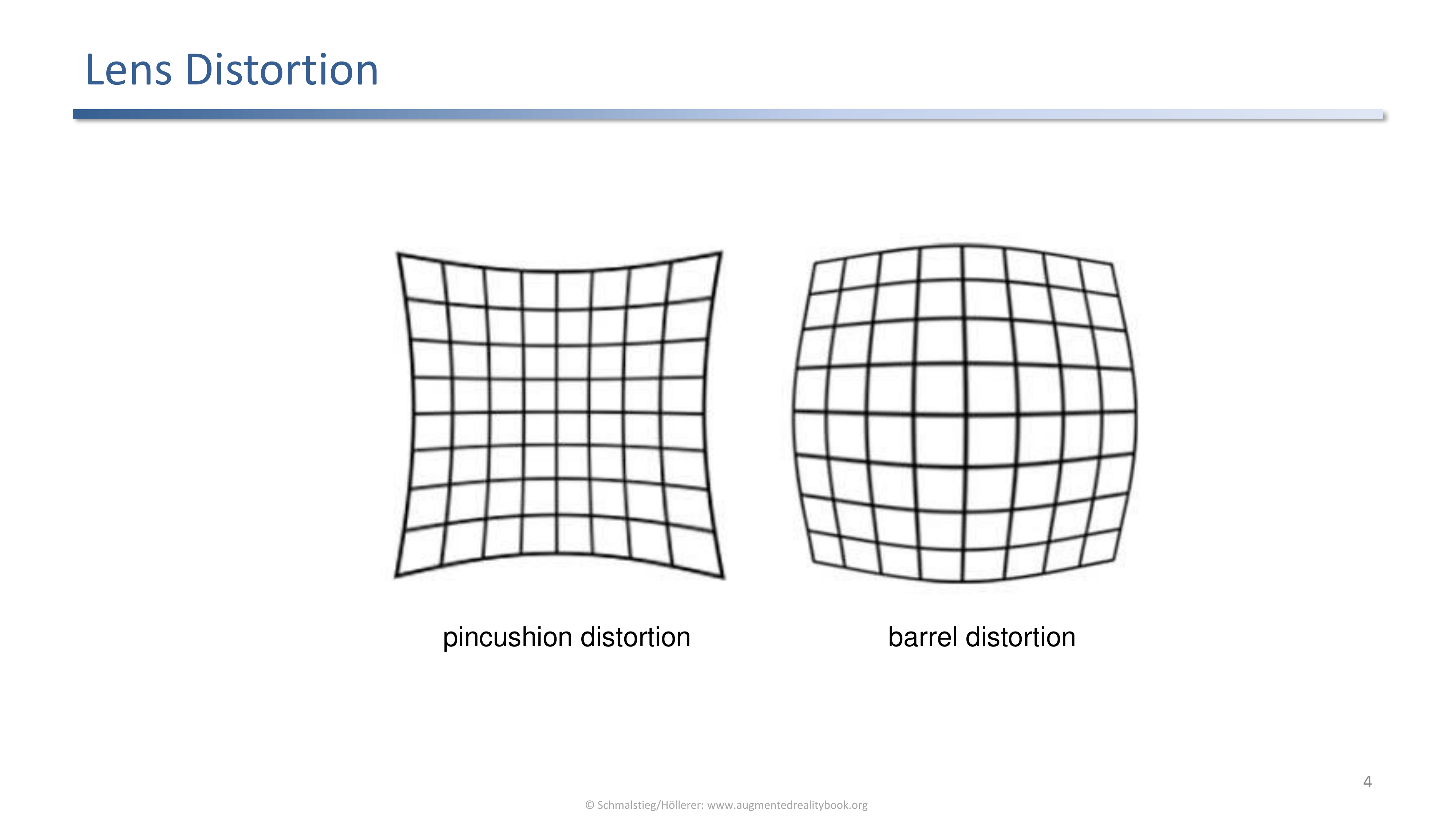
Pincushion distortion bends grid lines inward; barrel distortion bends them outward.
Real lenses bend straight lines. The two classic patterns on a regular grid:
- Pincushion distortion: lines bow inward toward the center.
- Barrel distortion: lines bulge outward away from the center.
Both effects grow toward the image edge and are typically modeled with a low-order radial polynomial parameterized by a few coefficients.
Video Undistortion
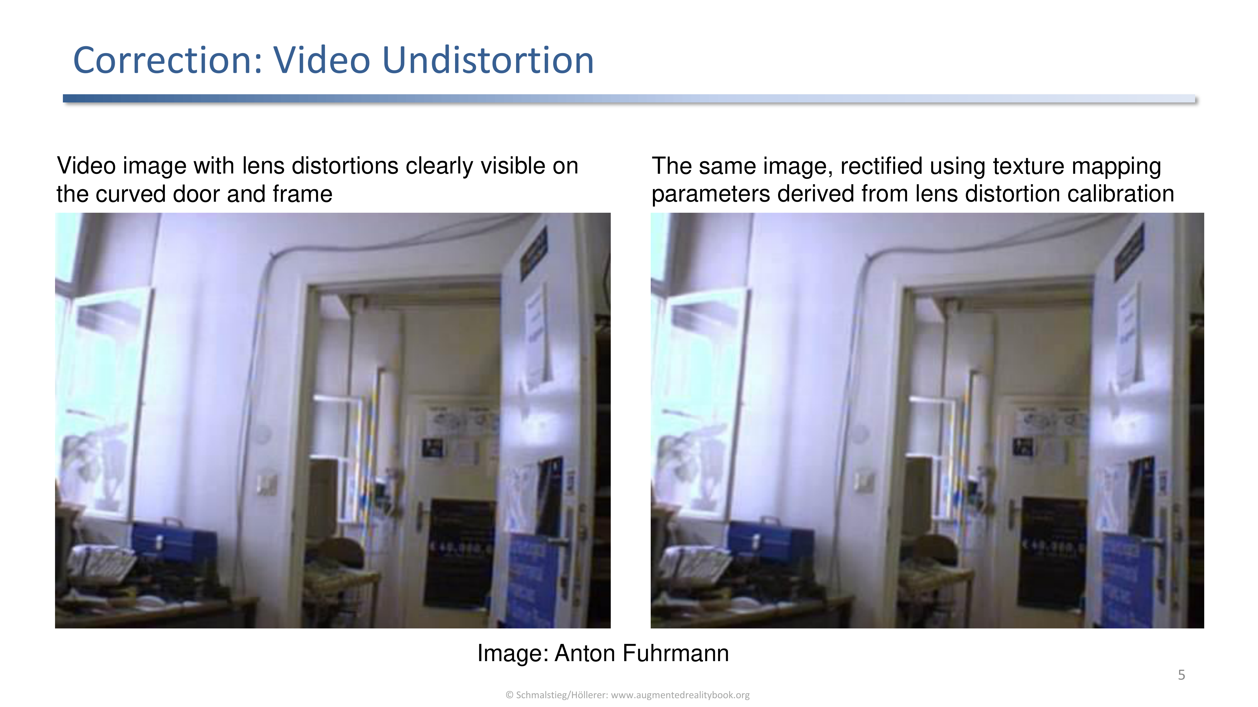
A raw video frame with a visibly curved door (left) and the same frame rectified using parameters from lens distortion calibration (right).
Once distortion parameters are known, the camera image can be rectified. In practice the undistortion is a texture-mapping pass on the GPU: each output pixel samples from the warped source location predicted by the inverse distortion model.
Calibration Target
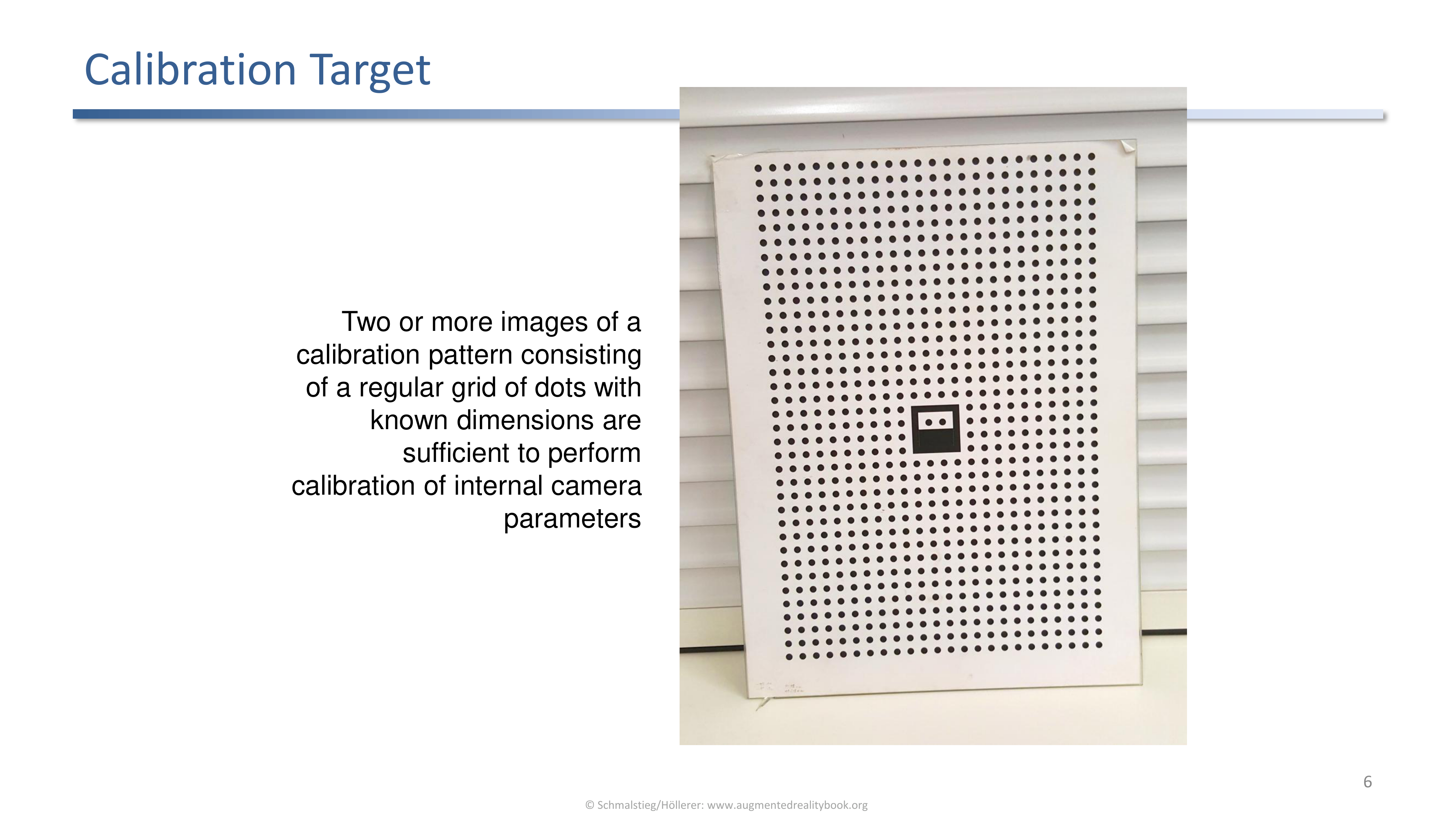
A regular grid of dots with known dimensions. Two or more views of this pattern suffice to recover internal camera parameters.
The target gives the system a known geometry to match against the observed pixel positions. Multiple views are needed because a single image leaves a depth and scale ambiguity that calibration cannot resolve.
2. Display Calibration
Display calibration finds the eye to display relation. Assumed static, done once, human-in-the-loop, with several setups varying user freedom.
For a head-mounted display the system needs to know where the user’s eye sits relative to the display. Key properties of this calibration:
- The eye to display relation is treated as static, so it only needs to be measured once at session start.
- It is a human-in-the-loop task: the system shows calibration patterns and asks the user to align them with real objects.
- Different setups give the user different amounts of freedom, which trades off accuracy against user effort.
Shooting Gallery
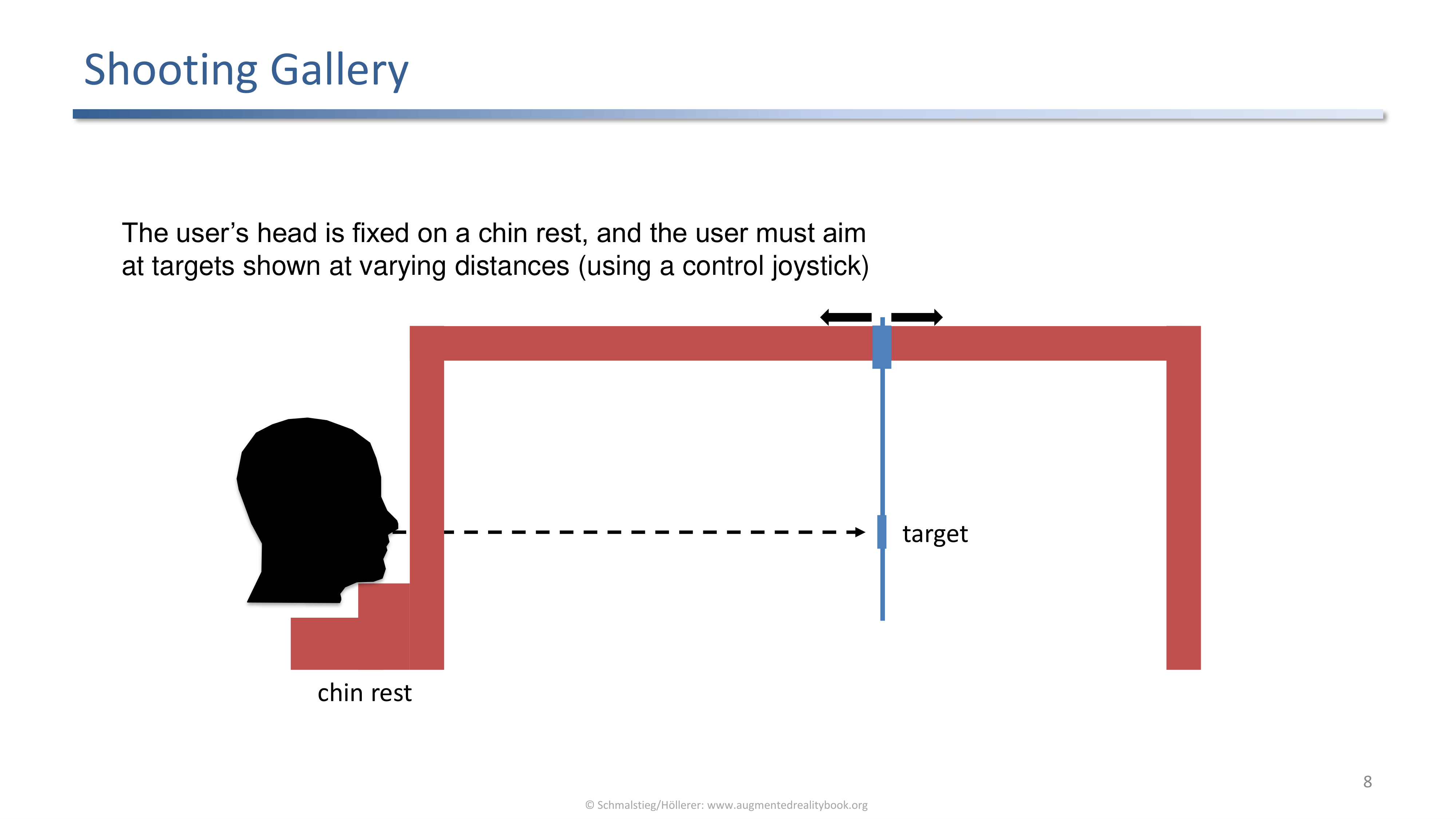
The user's head is fixed on a chin rest and a joystick aims at targets shown at varying distances.
The chin rest removes head motion as a variable; the joystick records where the displayed target ought to fall. It is accurate but rigid: the user must come to the rig.
Boresight
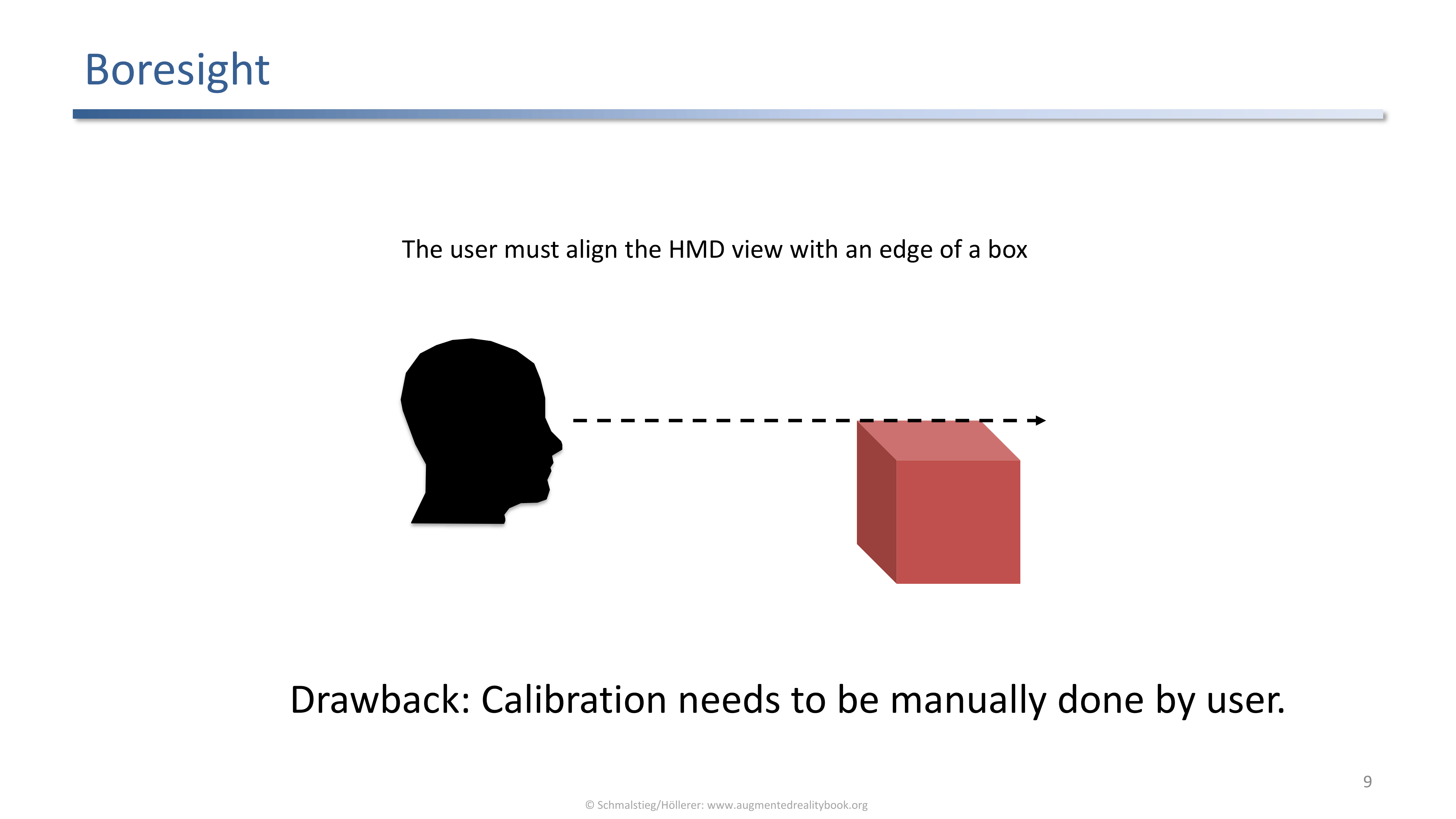
Boresight calibration asks the user to align the HMD view with an edge of a physical box. Drawback: must be done manually by the user.
Conceptually simple, but it inherits the same drawback as the shooting gallery: calibration is manual, slow, and error prone because every sample depends on the user’s alignment judgment.
Calibration by Eye Tracking
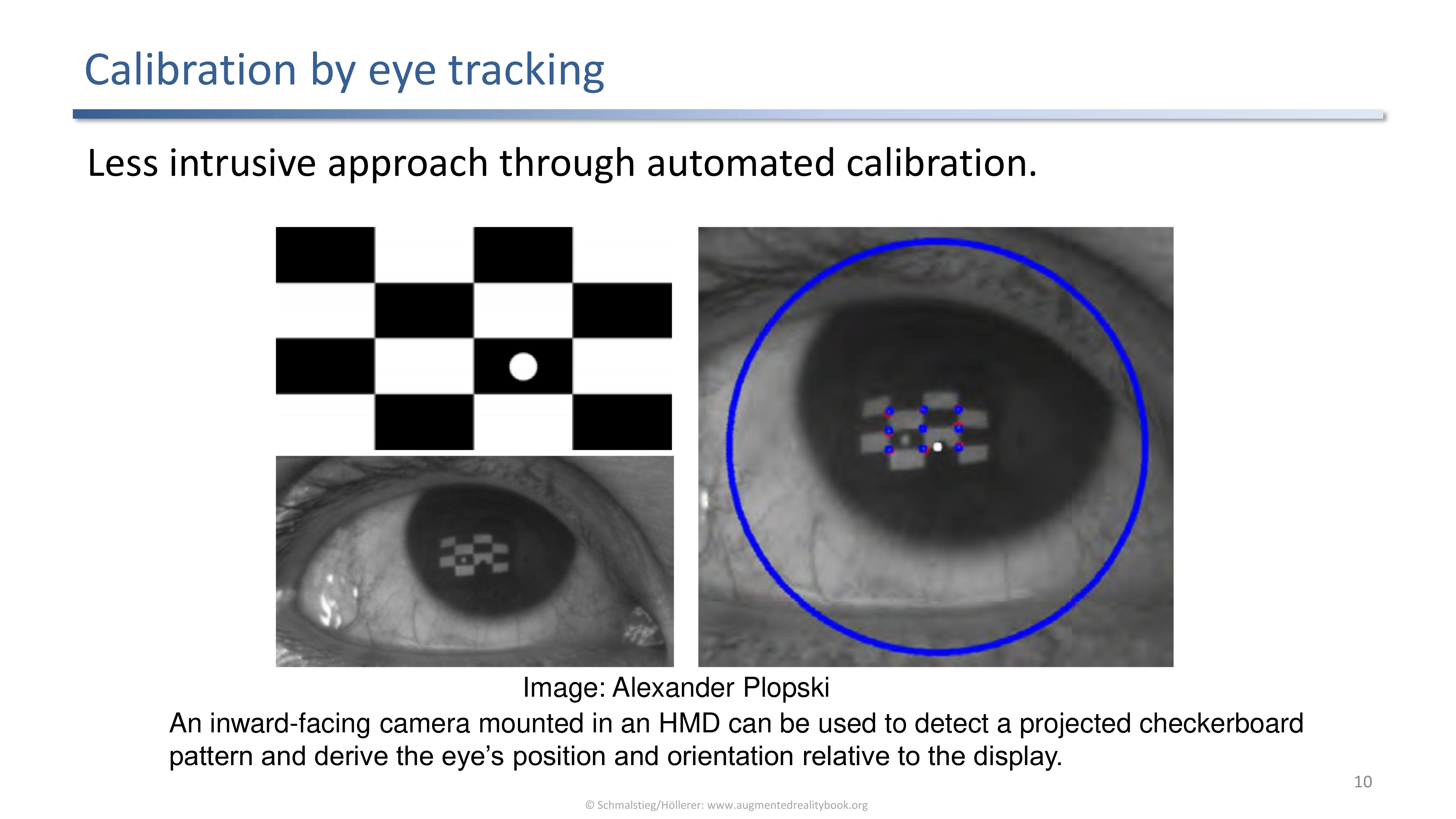
An inward-facing camera inside the HMD detects a projected checkerboard pattern on the eye and recovers the eye's position and orientation relative to the display.
A less intrusive approach: instead of asking the user to perform alignment, an inward-facing camera images the eye while the display projects a known pattern. The reflected pattern lets the system solve for eye position and orientation automatically.
SPAAM
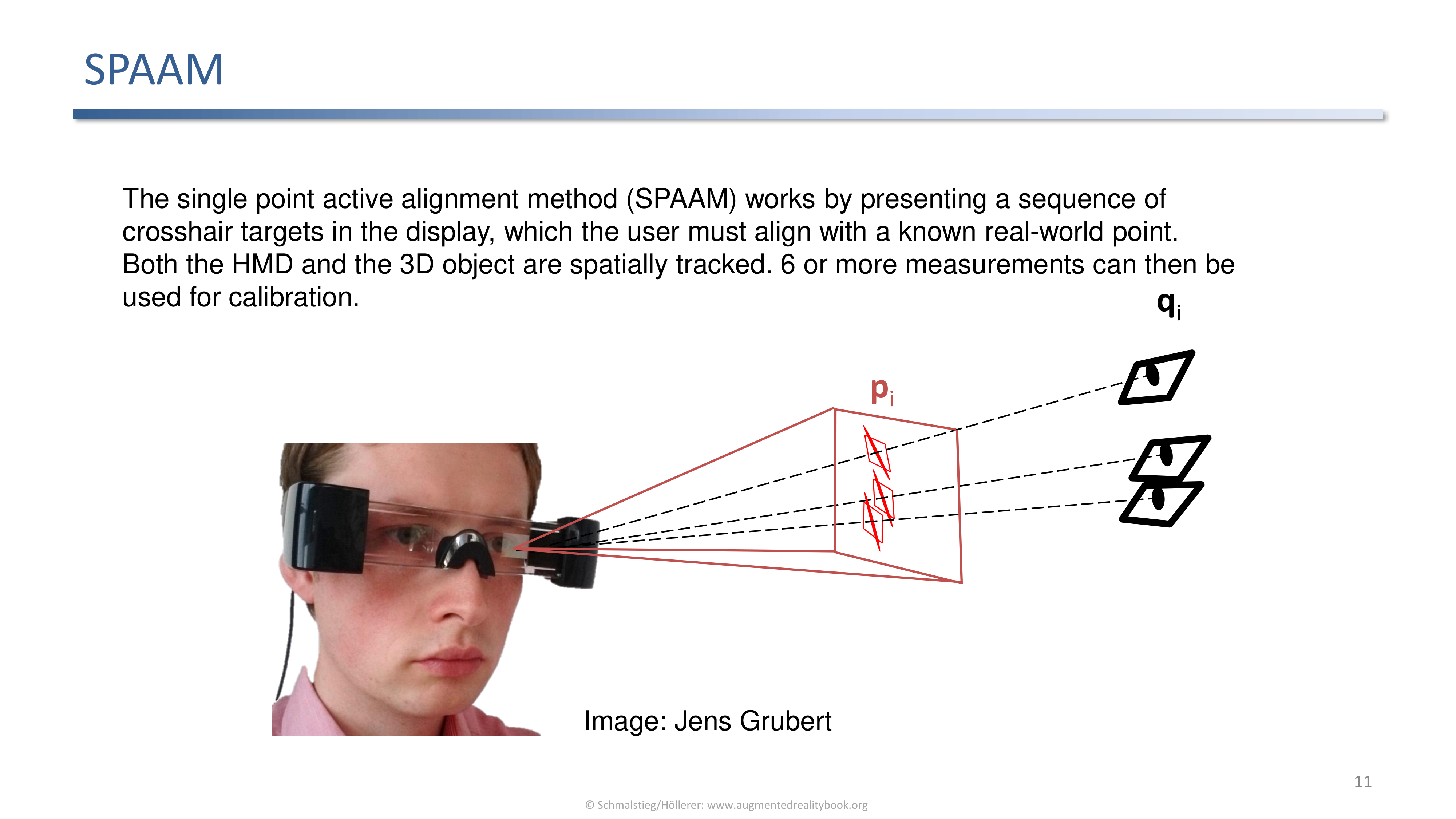
SPAAM presents a sequence of crosshair targets in the display and asks the user to align each one with a tracked real-world point. Six or more samples suffice for calibration.
The single point active alignment method needs both the HMD and a 3D object to be spatially tracked. Each alignment gives one display-to-world correspondence; with six or more correspondences the calibration parameters can be solved for in closed form.
Calibration with Input Device
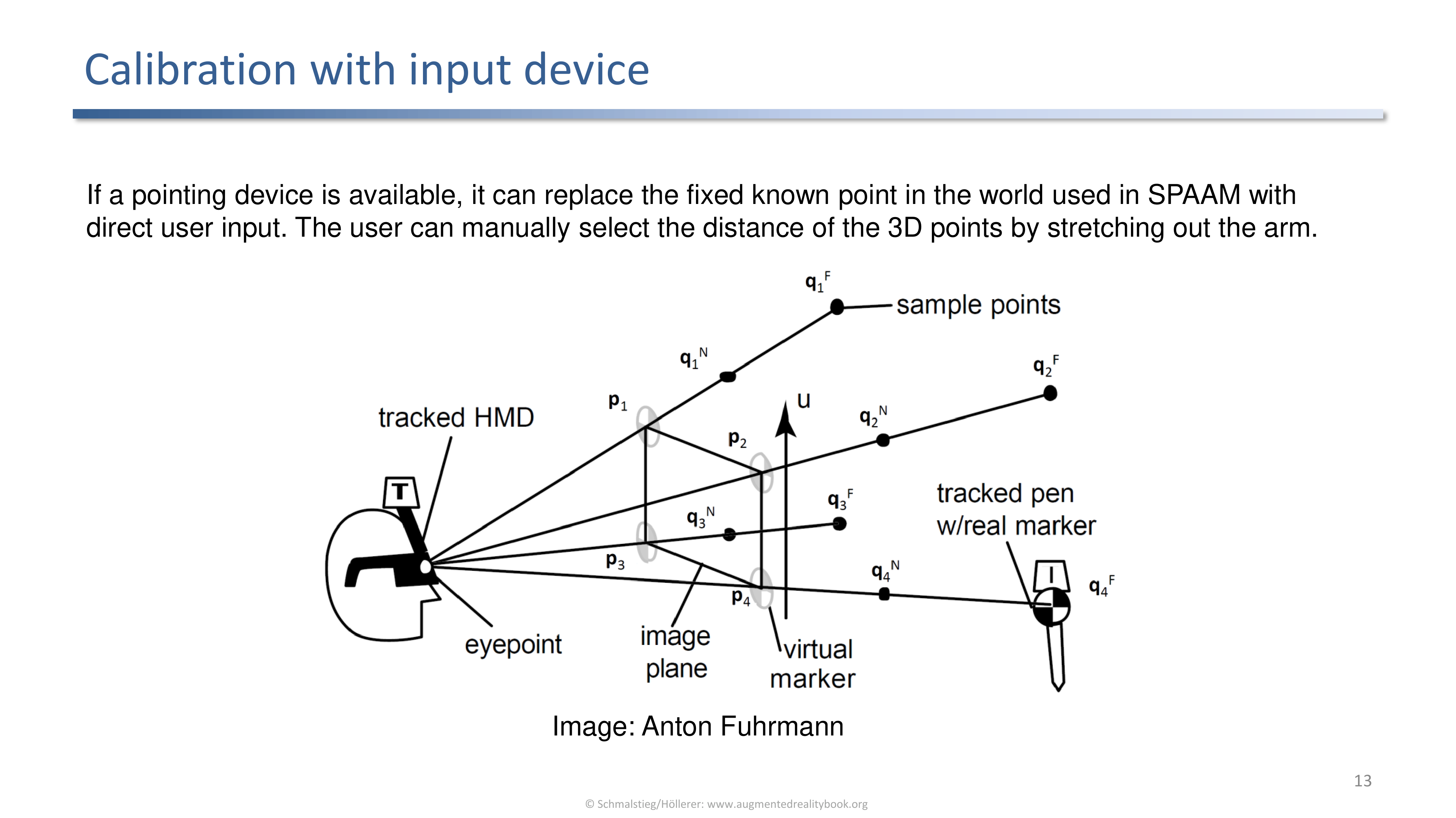
A tracked pen replaces the fixed real-world point of SPAAM. The user stretches the arm to select the depth of each sample point.
If a pointing device is available it can stand in for the fixed real-world point used in SPAAM. The user manually selects the distance of the 3D points by stretching out the arm holding the tracked pen, so the calibration covers a range of depths without needing fixed targets installed in the room.
3. Hand-Eye Calibration
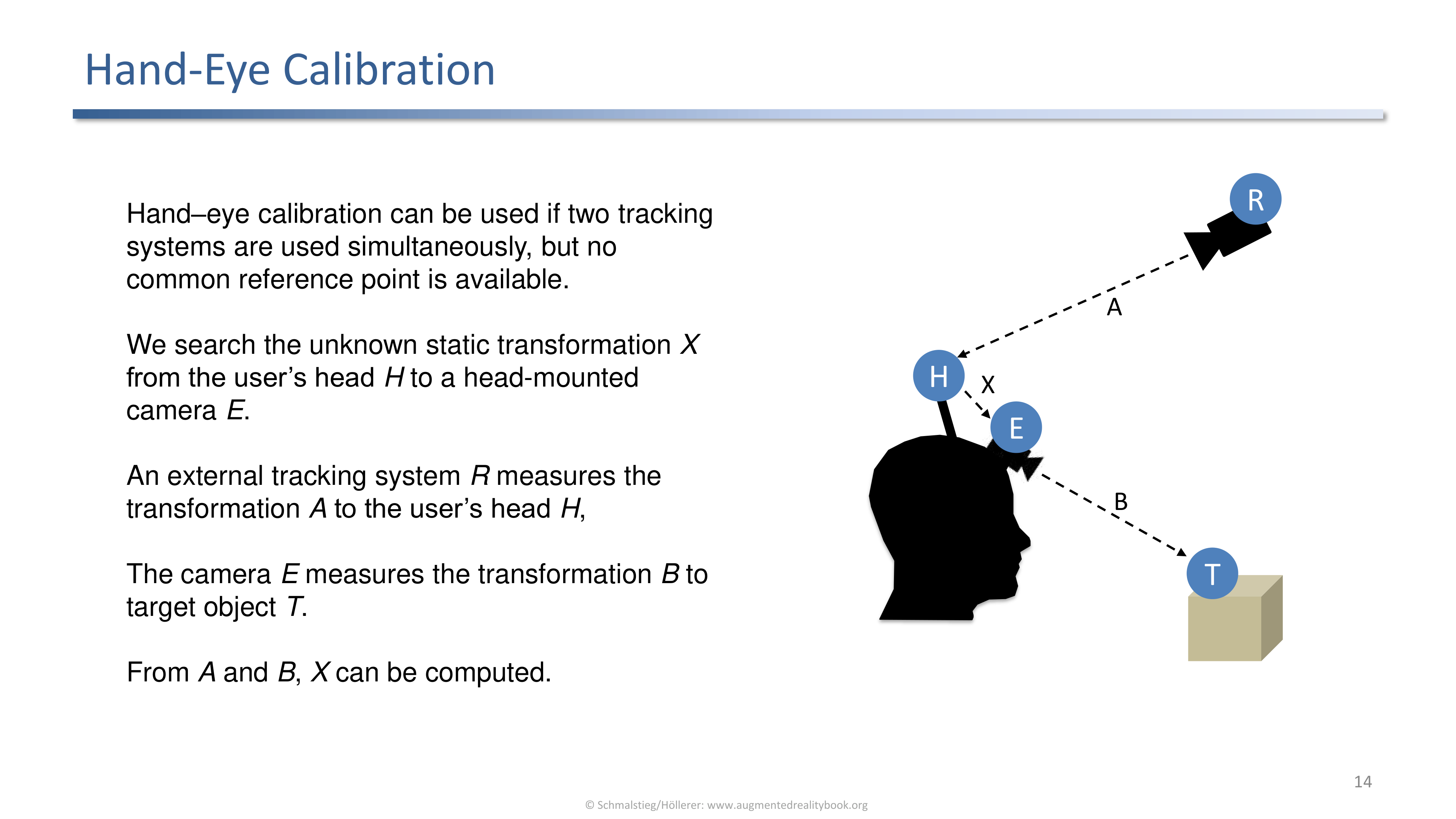
Hand-eye calibration solves for the unknown static transformation X between two tracking systems with no common reference point.
Hand-eye calibration applies when two tracking systems run at once but no common reference point is available. The unknown is the static transformation X from the user’s head H to a head-mounted camera E.
- External tracking system R measures transformation A to the user’s head H.
- Head-mounted camera E measures transformation B to a target object T.
- From a set of A and B measurements, X can be computed.
The classical formulation is the AX = XB problem, originally stated in robotics for the rigid relationship between a robot’s gripper (hand) and a camera (eye) mounted on it. In VR/AR the “hand” is the tracked HMD and the “eye” is a head-mounted camera.
4. Built-In Eye Trackers in Modern HMDs
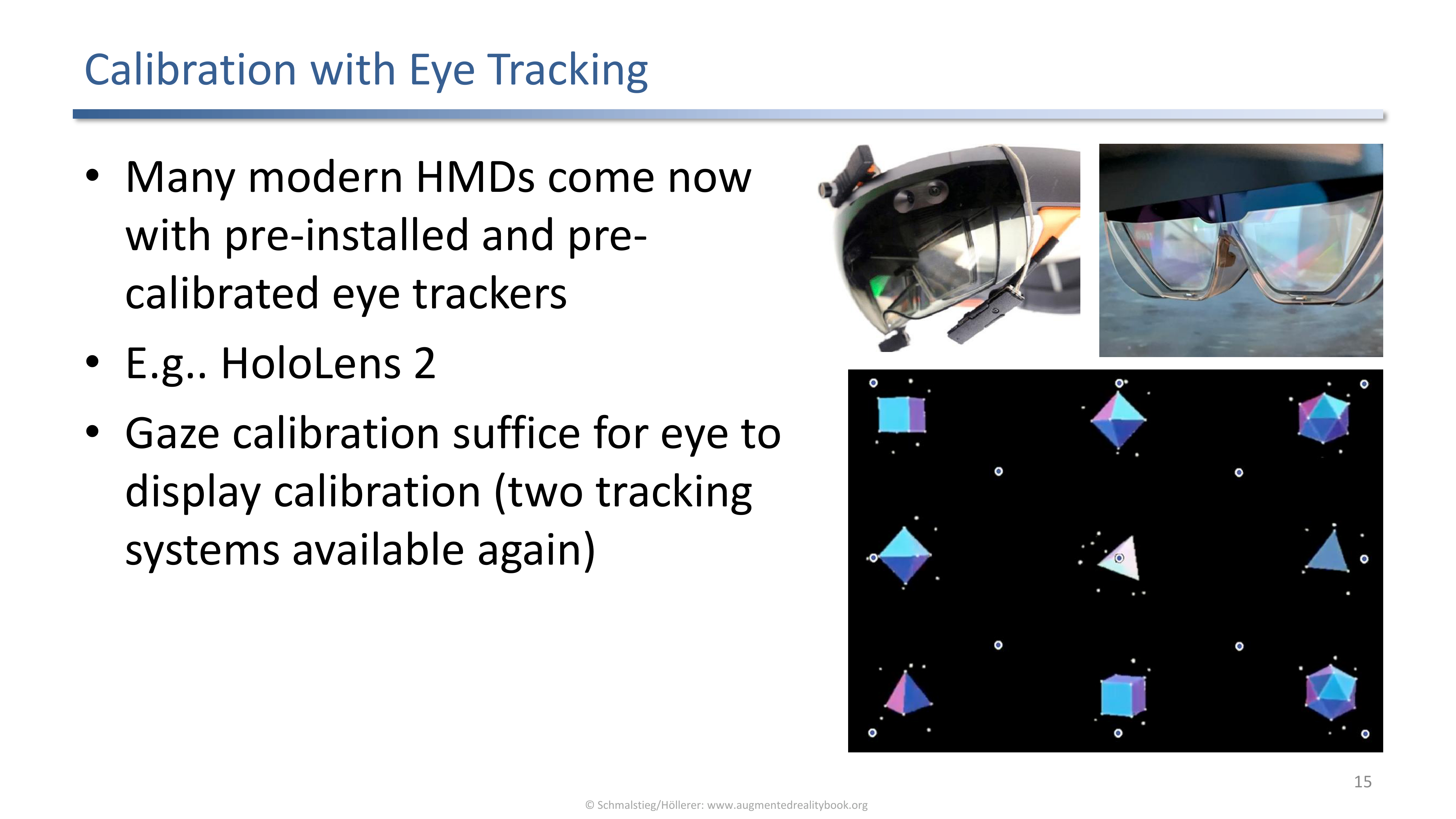
Modern HMDs such as the HoloLens 2 ship with pre-installed eye trackers. A gaze calibration is enough for eye-to-display calibration because two tracking systems are available again.
With an eye tracker already inside the device, the gaze calibration step provides one of the two tracked systems needed for the calibration math. Display calibration reduces to running this gaze step, removing the bespoke fixtures (chin rests, boxes, external pens) needed by the earlier methods.
HoloLens Eye Calibration Example
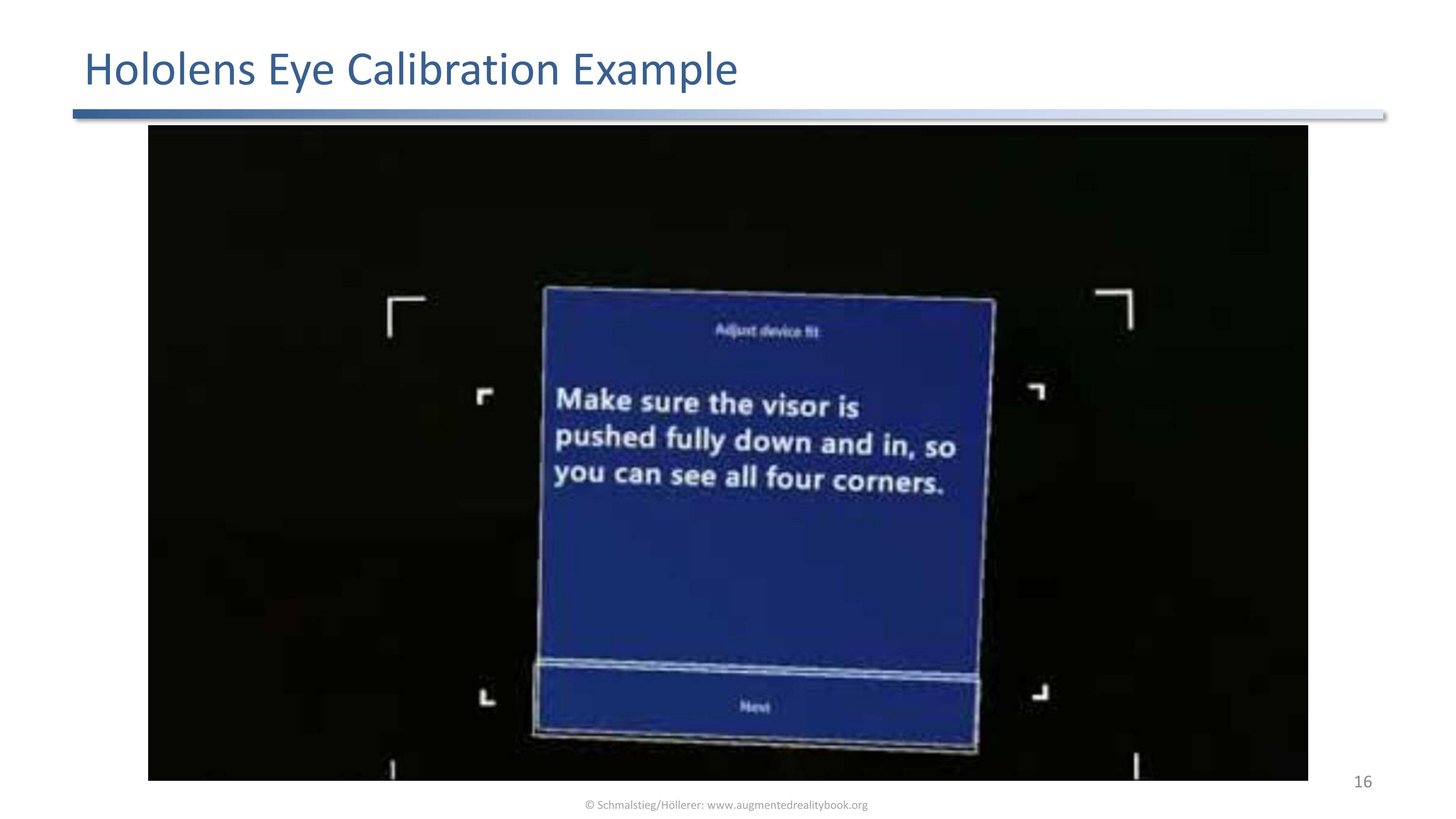
The HoloLens calibration screen asks the user to push the visor fully down so all four corner markers are visible, then walks the user through gaze calibration.
The on-device flow combines device fit and gaze calibration into a single short procedure. The user never sees the underlying math, which is exactly the point of pushing calibration into firmware.
5. Registration Errors After Calibration
Even with calibration done, two effects keep degrading registration quality: error propagation through the tracking chain, and end-to-end latency between sensing and display.
Error Propagation
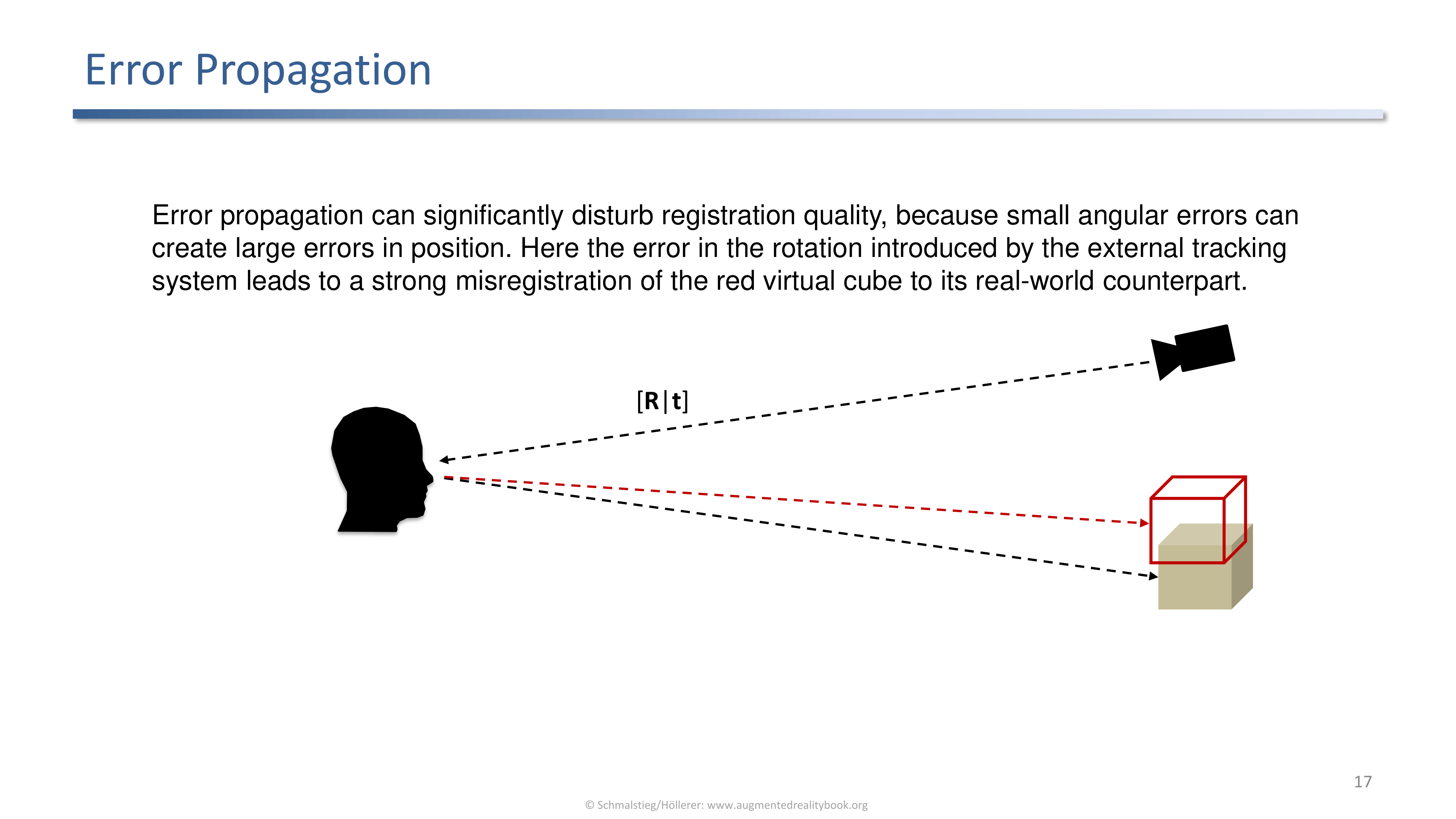
Small angular errors in the external tracking system propagate into large positional misregistration. The red virtual cube no longer sits on its real counterpart.
Long lever arms amplify angular uncertainty: a tiny rotation error at the head pose becomes a large positional offset at the far end of the line of sight. This is why rotation accuracy in the tracking pipeline matters more than position accuracy for visually convincing AR.
Latency Compensation
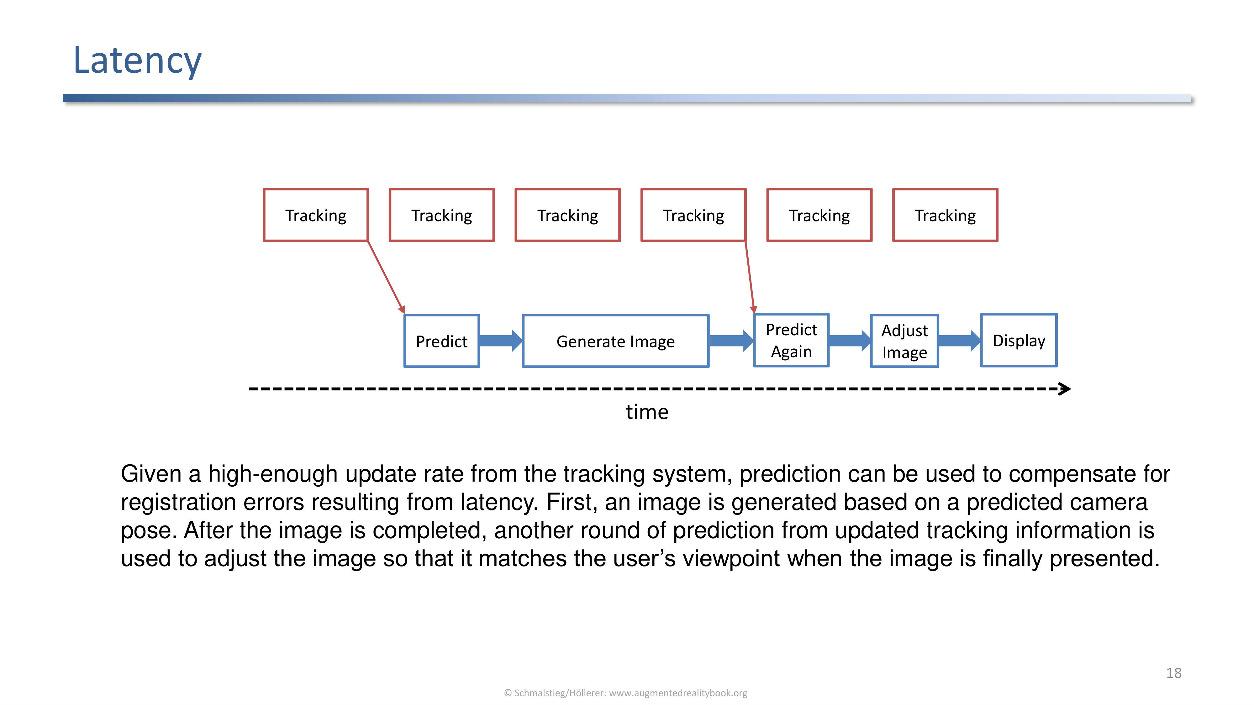
Given a fast enough tracking update rate, prediction hides latency: predict a pose, render, predict again from fresher data, adjust the image, then display.
Given a high enough update rate from the tracking system, prediction can hide the latency between tracking and display:
- Tracking samples arrive continuously.
- An image is generated from a predicted camera pose.
- After rendering, another round of prediction uses the latest tracking data.
- The image is adjusted (for example, reprojected) so it matches the user’s viewpoint at scan-out.
- Display.
This is the same idea as late-stage reprojection on consumer headsets: the rendered frame is warped just before display to compensate for the pose change that happened during rendering.
Applied Exam Focus
- What to calibrate: internal camera parameters, and the eye to display relation.
- Why: both are needed for correct registration of virtual content on the real world.
- Lens distortion: pincushion (inward) and barrel (outward); corrected by texture-mapped undistortion using calibrated parameters.
- Calibration target: regular dot grid with known dimensions, two or more viewpoints suffice.
- Manual display calibration: shooting gallery (chin rest + joystick), boresight (align with box edge); both manual and error prone.
- SPAAM: align crosshair targets in the display with a tracked real-world point, six or more samples.
- Pointing device calibration: replaces the fixed point with a tracked pen, lets the user choose sample depths.
- Eye-tracking calibration (research): inward-facing camera images the eye to remove manual alignment.
- Hand-eye calibration: solve for X from external pose A and camera pose B, the AX = XB problem.
- Modern HMDs: built-in eye trackers reduce display calibration to a gaze calibration step.
- Error propagation: small angular errors blow up into large positional offsets at distance.
- Latency: predict pose, render, predict again, reproject, display.
Self-Check
- Why does AR need both camera calibration and display calibration?
Answer
Camera calibration recovers the internal optical parameters and lens distortion so the captured image becomes a clean projection. Display calibration recovers where the user’s eye sits relative to the HMD optics, so virtual content projected to the display lands on the same line of sight as the real point. Both are needed for registration: one fixes the input video, the other fixes the output projection to the eye.
- What is the difference between pincushion and barrel distortion?
Answer
Both are radial lens distortions that grow toward the image edge. Pincushion bends straight grid lines inward toward the image center, while barrel bows them outward. They are modeled with a low-order radial polynomial and removed by undistorting the video with the calibrated coefficients.
- Why is a regular dot grid a useful calibration target, and why are multiple views needed?
Answer
The dot grid has known geometry, so observed pixel positions of the dots give correspondences to known 3D points. Multiple views are needed because a single image leaves depth and scale ambiguities; varying the viewpoint introduces enough constraints to solve for the internal parameters.
- What is the drawback shared by shooting gallery and boresight calibration?
Answer
Both are manual, human-in-the-loop procedures. Every sample depends on the user’s alignment judgment, so accuracy is bounded by user attention and patience. The shooting gallery also requires a specific rig (chin rest plus joystick), and boresight depends on a calibrated physical box edge.
- How does SPAAM differ from calibration with an input device?
Answer
SPAAM aligns crosshair targets shown on the display with a single tracked real-world point, repeated six or more times from different head poses. Calibration with a tracked pointing device replaces that fixed real-world point with a tracked pen, so the user can pick sample depths by stretching the arm. The math is the same; the pen gives more flexible sampling without installed targets in the room.
- What does hand-eye calibration solve, and why is it relevant when two tracking systems are used?
Answer
It solves the unknown static transformation X between two tracked frames (here, the user’s head H and a head-mounted camera E) when no shared reference point is available. With external tracker measurements A (R to H) and camera measurements B (E to T) collected from multiple poses, X is recovered from the AX = XB constraint. It applies whenever two trackers run in parallel but cannot directly compare measurements.
- Why does small angular error in tracking become a large positional error at distance?
Answer
Angular error rotates the entire viewing ray, so the positional offset at a virtual object grows linearly with its distance from the user. Long lever arms amplify the rotation: a fraction-of-a-degree wobble at the head produces centimeters of misregistration on an object meters away. This is why rotational accuracy matters more than positional accuracy for visually convincing AR.
- How does prediction compensate for end-to-end latency in the rendering pipeline?
Answer
The pipeline predicts twice. First it predicts the future pose at scan-out time and renders for that pose. After rendering, fresh tracking data is used to predict the latest pose, and the rendered frame is reprojected to match it before display. A high tracker update rate keeps both predictions accurate so the final warp stays small.