Previous: (y-07) Calibration and Registration | AR Index | Next: (y-09) Perception and Psychology
Mental Model First
- VR rendering has full geometric knowledge of the scene. Occlusion, lighting, shadows, and camera parameters all fall out of standard graphics.
- AR rendering does not. The final image is a composite of video and rendered content, so every visual coherence cue (occlusion, illumination, shadows, reflections, refractions, camera matching) has to be either faked or reconstructed.
- The lecture walks through one cue at a time: occlusion, then illumination, then shadows, then reflections and refractions, then deliberate visual effects (diminished reality, stylization), and finally camera effects.
- Recurring trick across all topics: get a phantom of the real scene (model, depth map, segmentation mask, or a learned proxy) and use it to drive the renderer the same way VR would.
1. VR vs AR Rendering
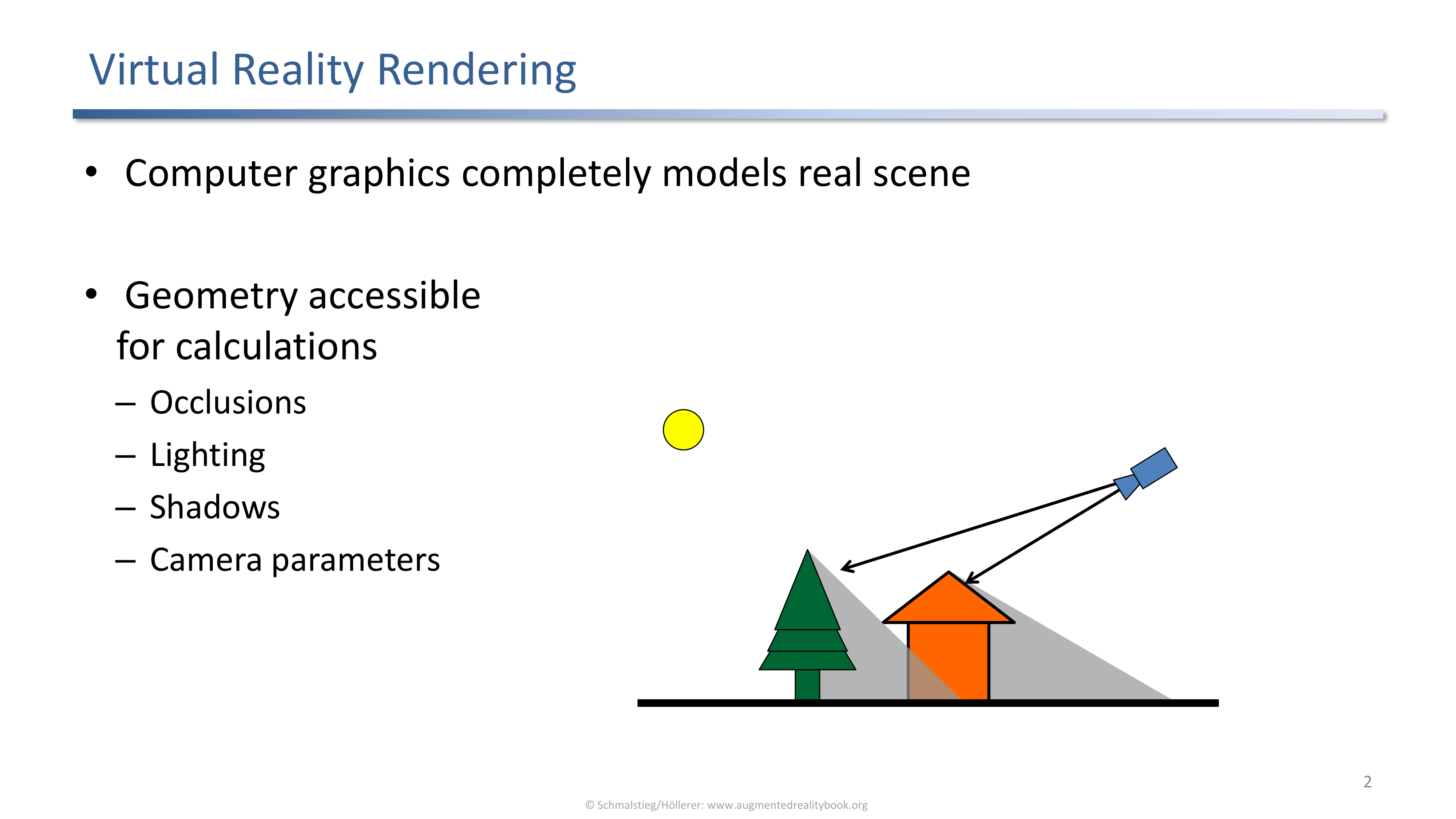
VR rendering: the scene is fully modeled in computer graphics, so geometry is accessible for occlusion, lighting, shadow, and camera calculations.
In virtual reality the system has a complete CG model of the scene. Geometry is fully accessible, so occlusions, lighting, shadows, and camera parameters can be computed directly from the model.
AR Rendering Composites Limited Information
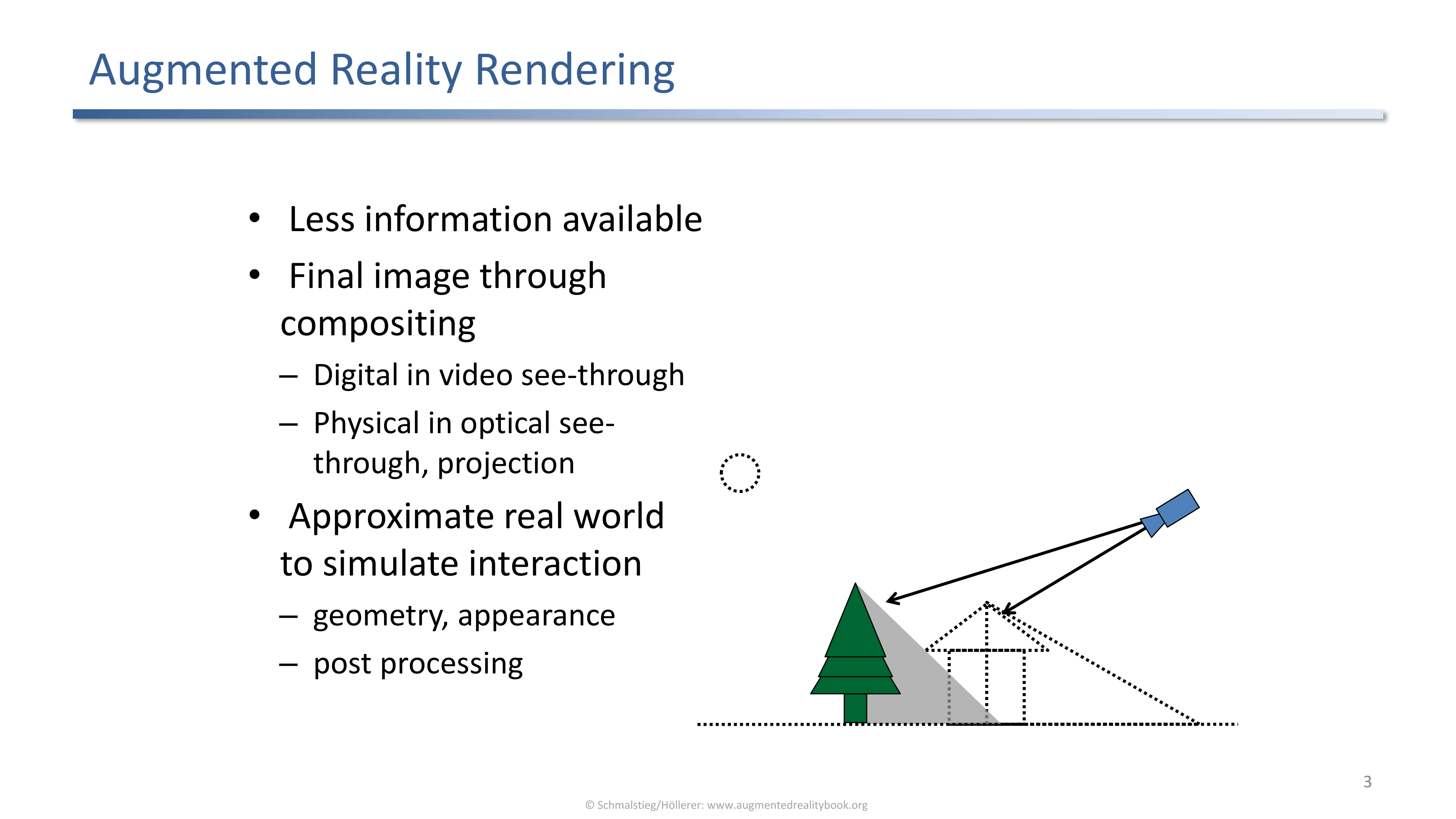
AR rendering: much less information is available; the final image is produced by compositing (digital in video see-through, physical in optical see-through and projection).
The system has to approximate the real world to simulate interaction. The compositing step is what produces the final frame:
- Digital compositing in video see-through HMDs.
- Physical compositing in optical see-through HMDs and projection systems.
A Compositing Example
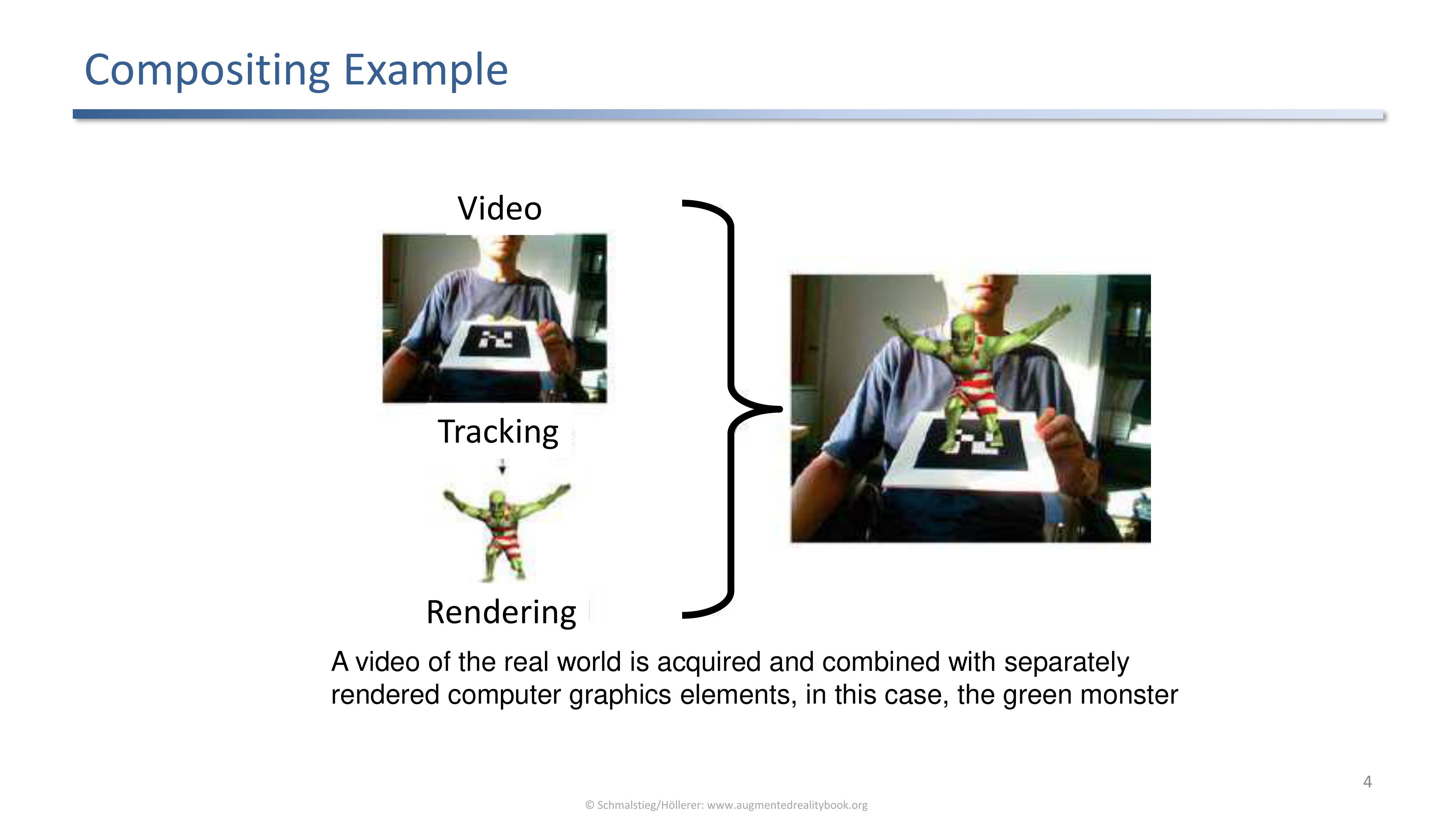
Video of the real world is captured, tracking provides a pose, the green monster is rendered separately, and renderer plus video are combined into the final frame.
The four-stage block diagram (video, tracking, rendering, compositing) is the spine of every later technique in the lecture. Whatever cue we are trying to add (occlusion, lighting, shadow) plugs into one of those stages.
Recall: Depth Cues
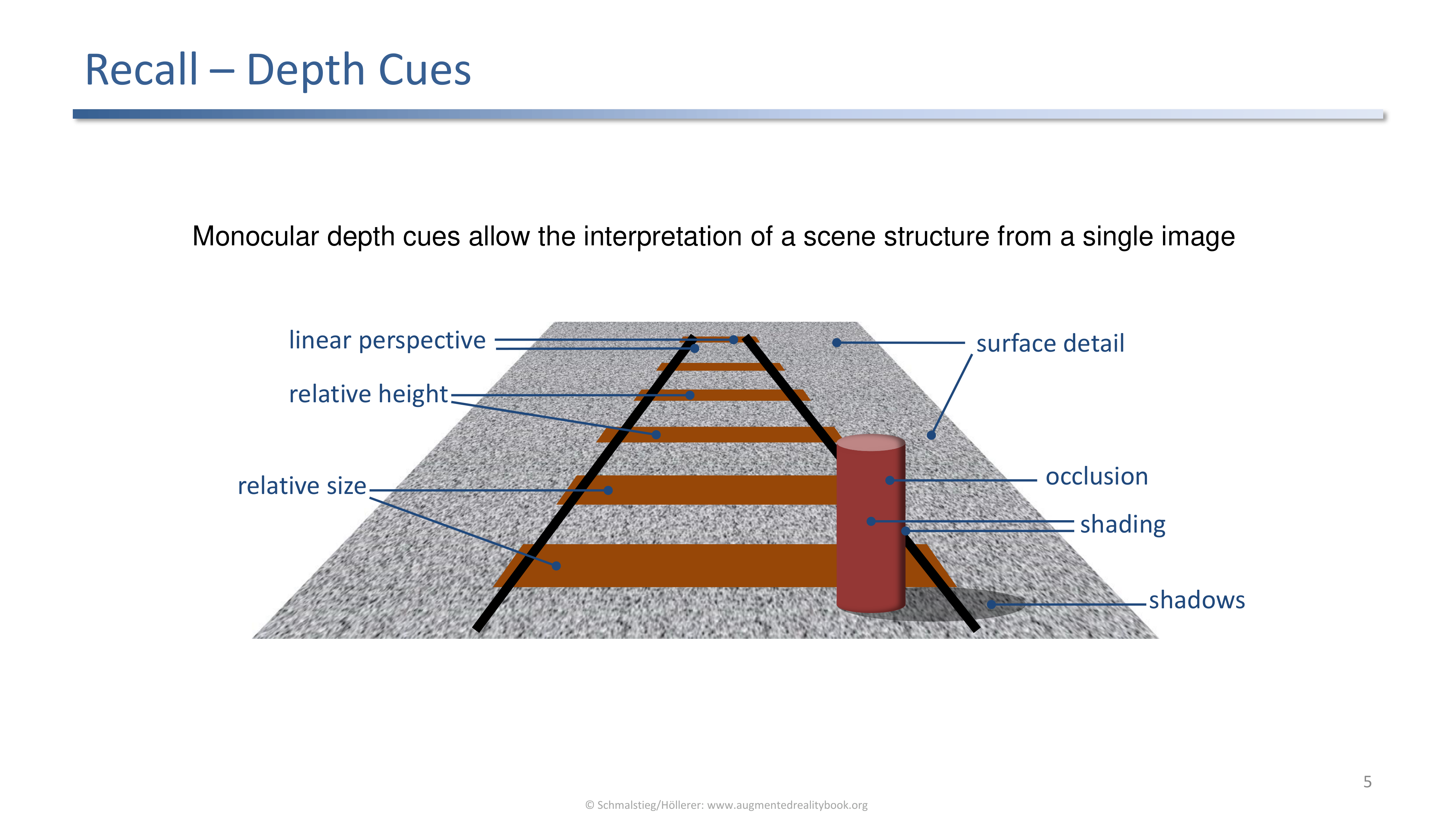
Depth in the final image relies on occlusion, shading, shadows, surface detail, linear perspective, relative height, and relative size.
Visual coherence techniques try to deliver these cues even when the AR system does not have full scene geometry. The sections that follow each pick one of these cues and work backwards to whatever reconstruction is required.
2. Occlusion
Virtual In Front Of Real, Virtual Behind Real
Virtual in front of real is easy (draw on top). Virtual behind real needs an extra strategy to distinguish visible from occluded augmentations.
If the virtual object is in front of the real, drawing the augmentation on top of the video background already looks correct. If it is behind real geometry, the renderer needs some representation of that geometry.
Occlusion Example
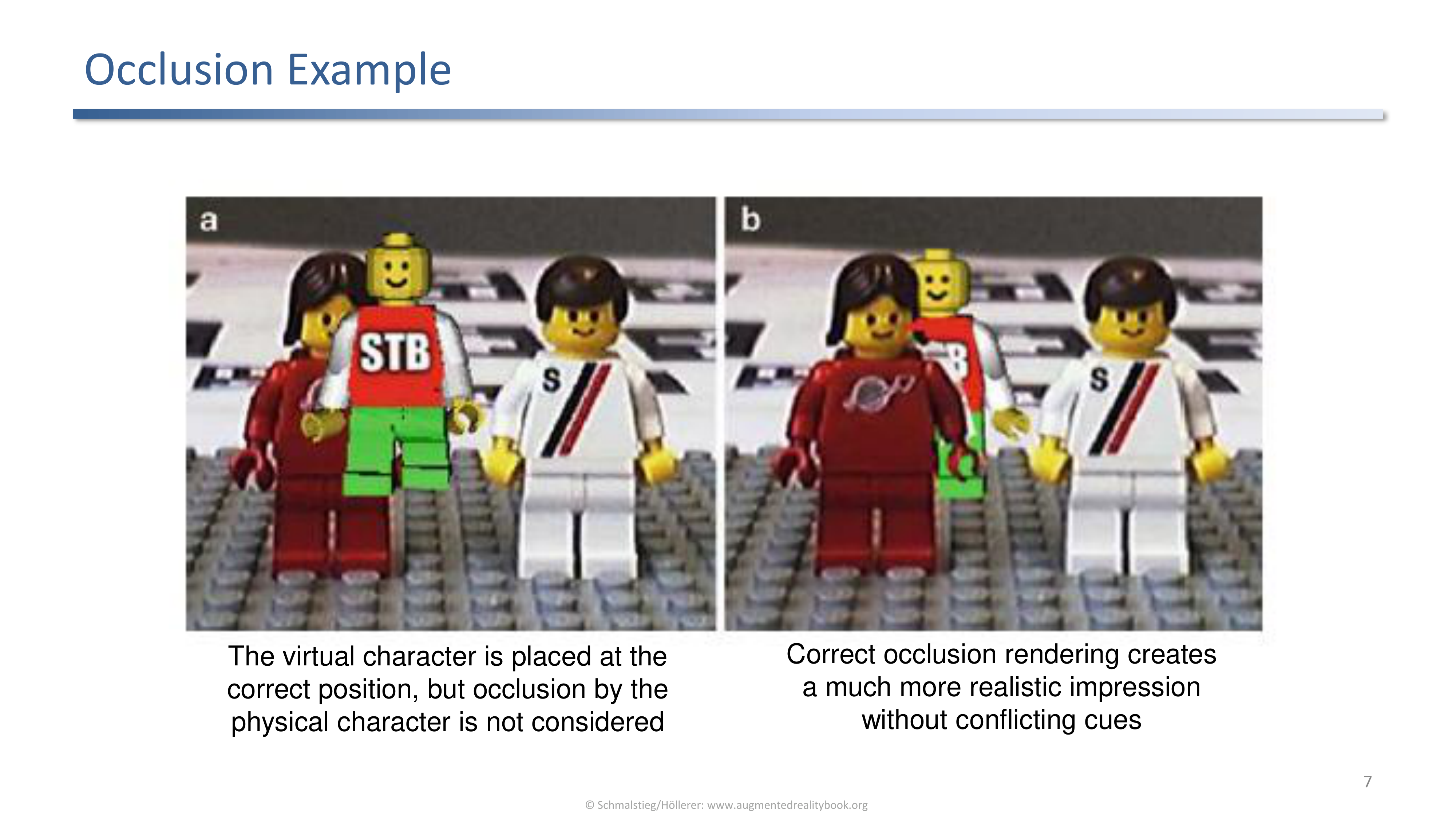
Without occlusion the virtual character is registered correctly but visibly floats; with occlusion the virtual character disappears behind the real one as expected.
Registration alone is not enough. Without occlusion the depth cues conflict (the virtual character is at the right position but is not hidden by the foreground real character) and the brain notices. Correct occlusion rendering produces a much more realistic impression.
Phantom Rendering
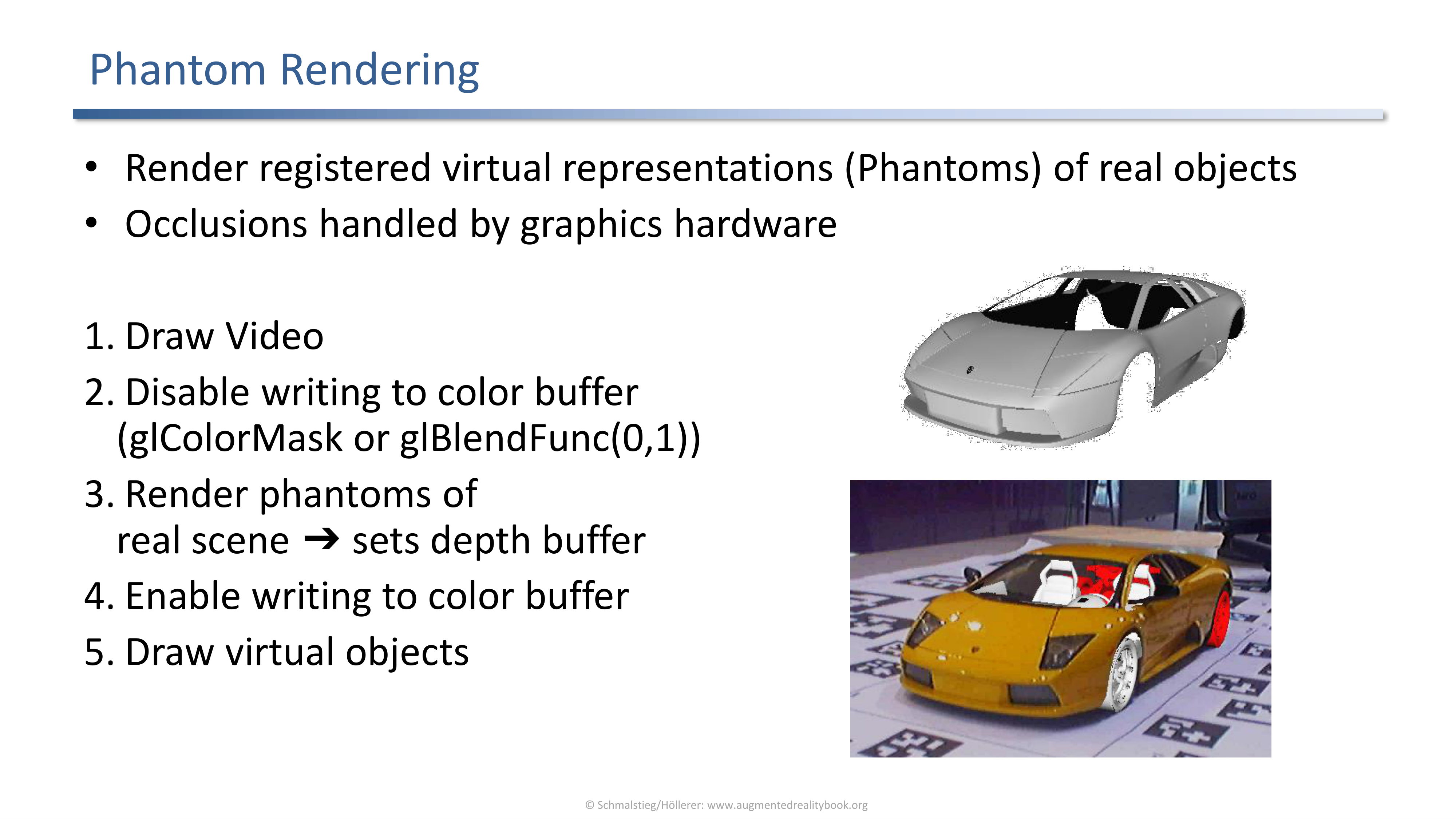
Phantom rendering: registered virtual representations of real objects (phantoms) drive the depth buffer so the GPU resolves occlusion automatically.
The pipeline:
- Draw the video.
- Disable writing to the color buffer (for example with
glColorMaskorglBlendFunc(0,1)). - Render the phantoms of the real scene so they only set the depth buffer.
- Enable writing to the color buffer again.
- Render the virtual objects normally. The depth test now hides them behind the real geometry that the phantoms represent.
Problems of Phantom Rendering
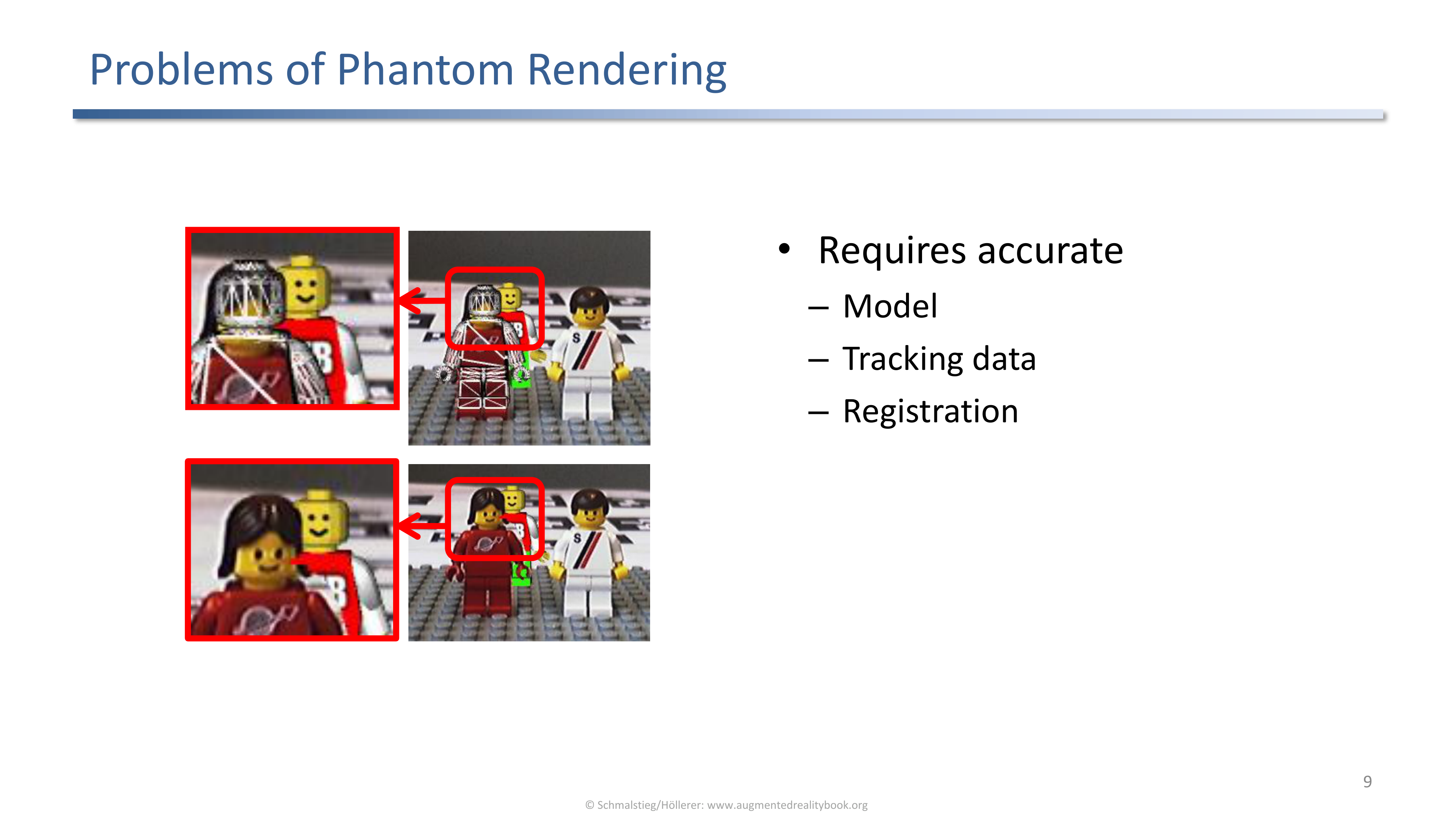
Phantom rendering requires accurate model, tracking data, and registration. Any of the three being off produces visible misalignment around the occlusion boundary.
Phantom rendering pushes the burden onto the modelling and tracking pipelines. When the phantom is slightly wrong, the seam between real and virtual looks broken in a way that the user immediately reads as fake.
Edge Occlusion Pipeline
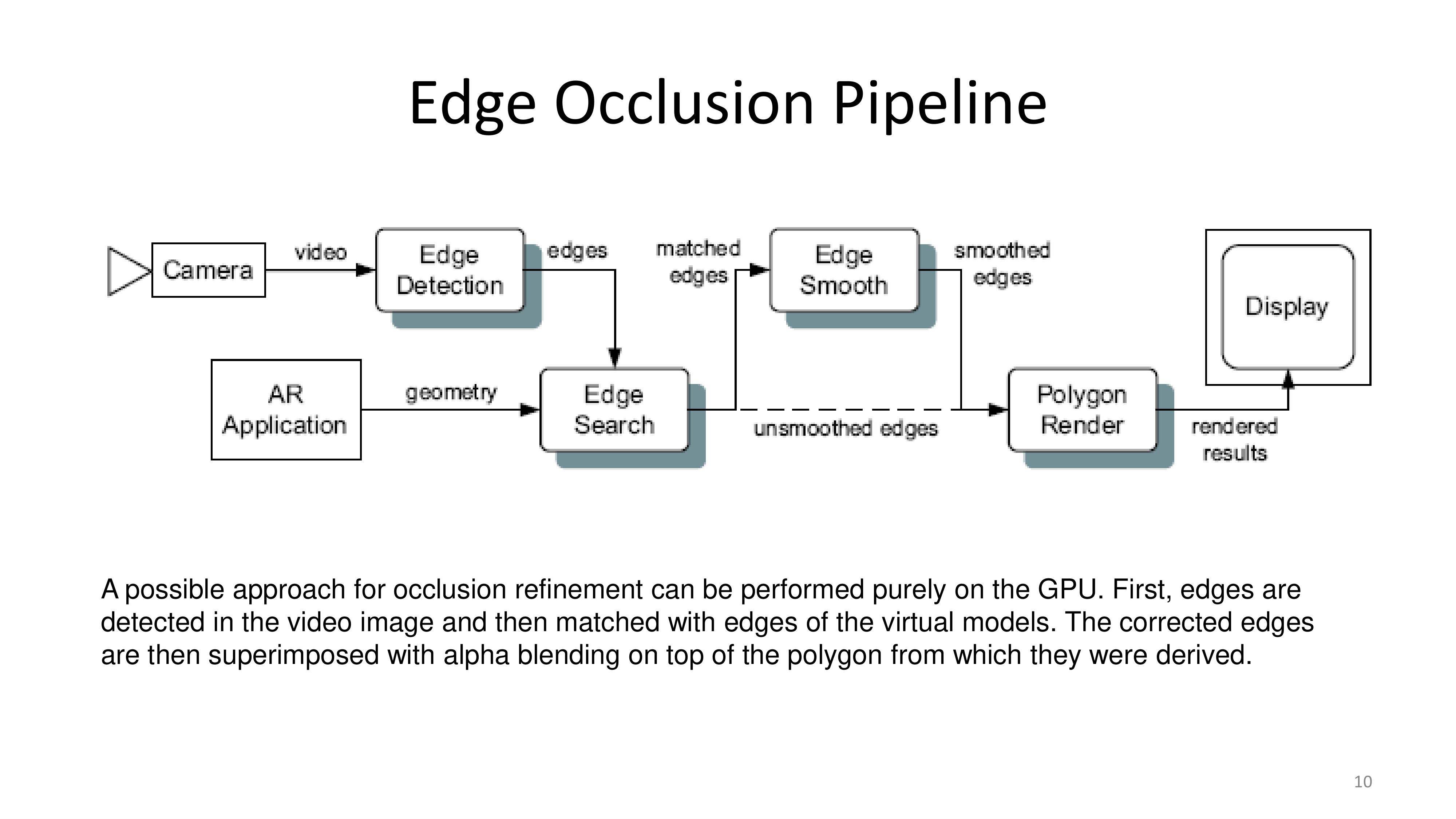
Edge occlusion runs purely on the GPU: detect edges in the video, match to projected edges of the virtual model, alpha-blend the corrected edges back onto the polygons.
Edge occlusion is a refinement that hides phantom inaccuracies. Instead of trusting the phantom geometry exactly, it lets the video pixels override the silhouette wherever the model is a bit off.
Edge Occlusion Example
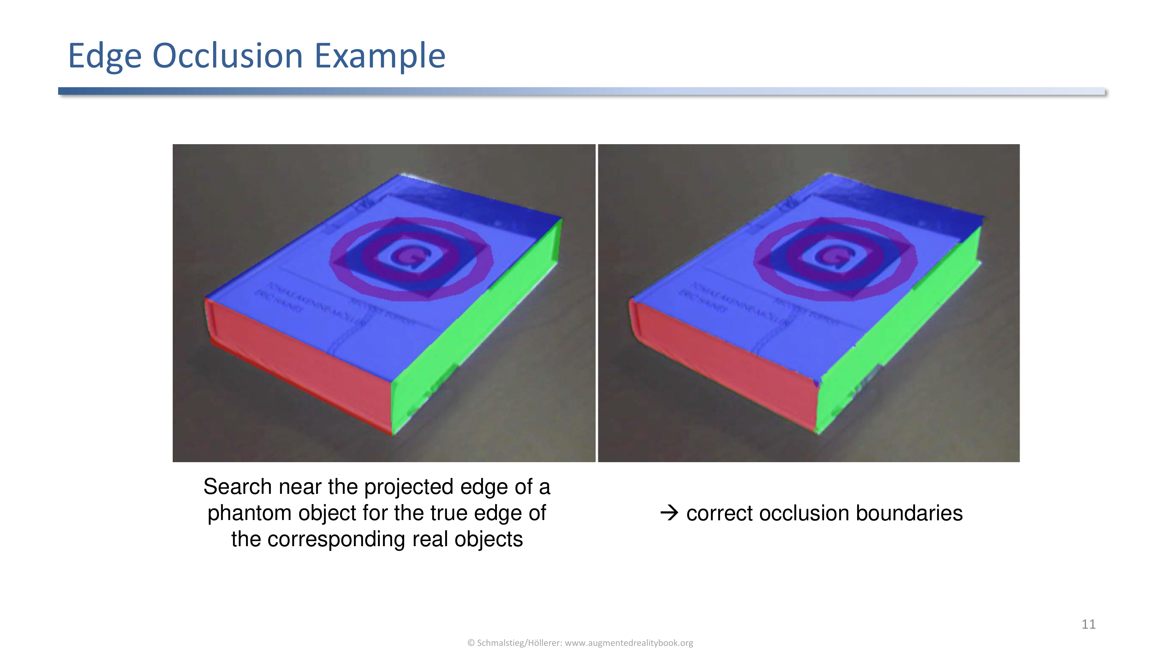
Near a projected phantom edge the algorithm searches the video for the true edge of the real object so the occlusion boundary tracks the real contour.
The result: occlusion boundaries snap to real features in the image even when the underlying phantom mesh is approximate.
Probabilistic Occlusion Handling
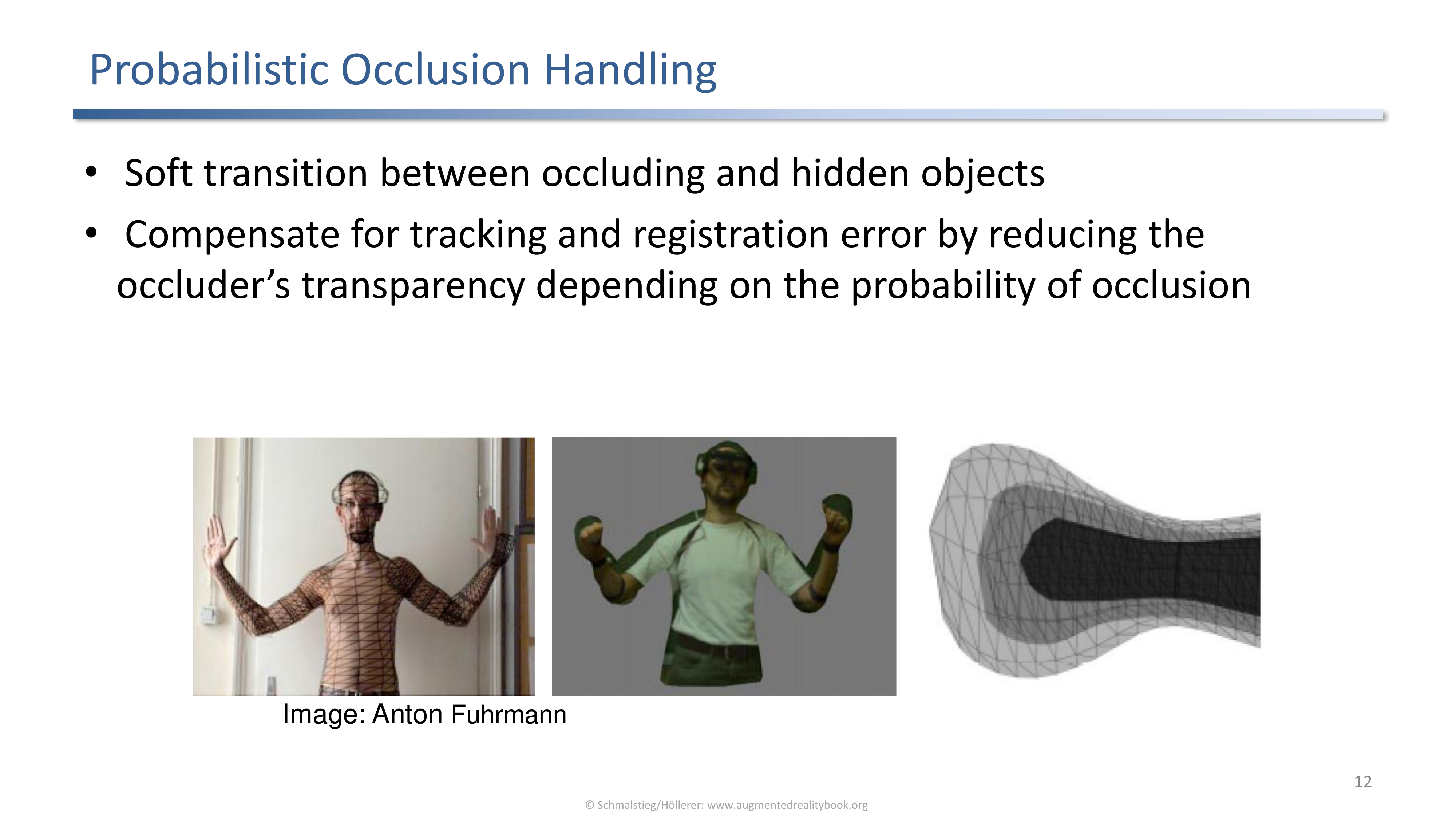
Probabilistic occlusion: the occluder's transparency softens with the probability of occlusion, so tracking and registration errors fade instead of tearing.
Soft transitions are visually forgiving. Rather than a sharp seam in the wrong place, the user sees a gradual blend that the eye reads as motion blur or depth uncertainty.
Model-Free Occlusion
No phantom model: depth is reconstructed directly from the video using stereo, shape-from-shading, or structured light.
When no phantom mesh is available the depth map can be reconstructed online. The performance budget is the dominant constraint because the depth estimator has to keep up with the camera frame rate.
Depth Image Phantom Rendering
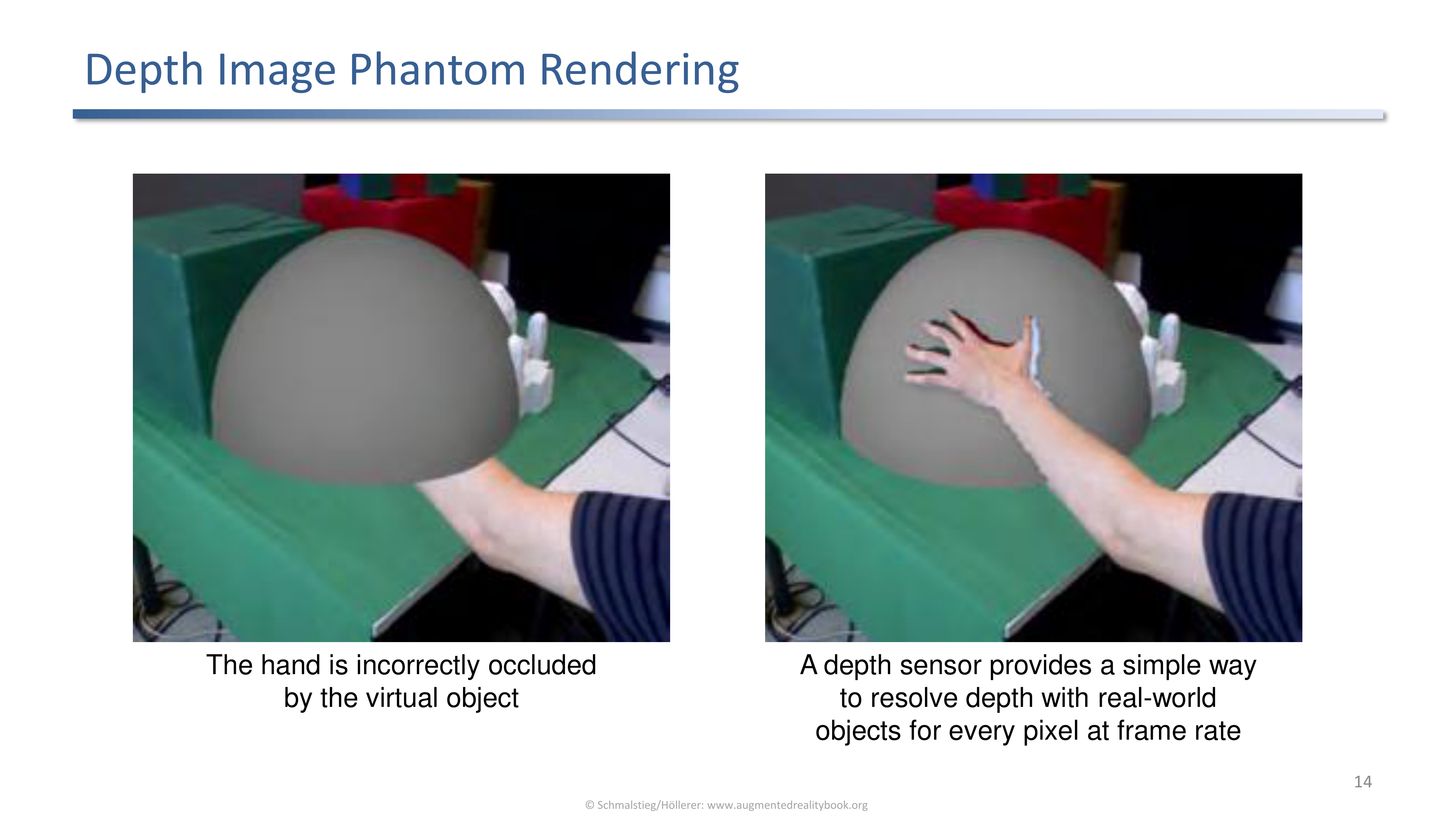
A depth sensor delivers per-pixel depth at frame rate, but misregistration between depth and video still causes wrong occlusions (here the hand is incorrectly behind the virtual object).
A consumer depth sensor (Kinect-style, ToF, LiDAR on modern phones) gives free per-pixel depth. The remaining problem is the alignment between the depth stream and the colour stream. Where alignment breaks, the depth-based occlusion goes wrong.
Virtual Studio Occlusion
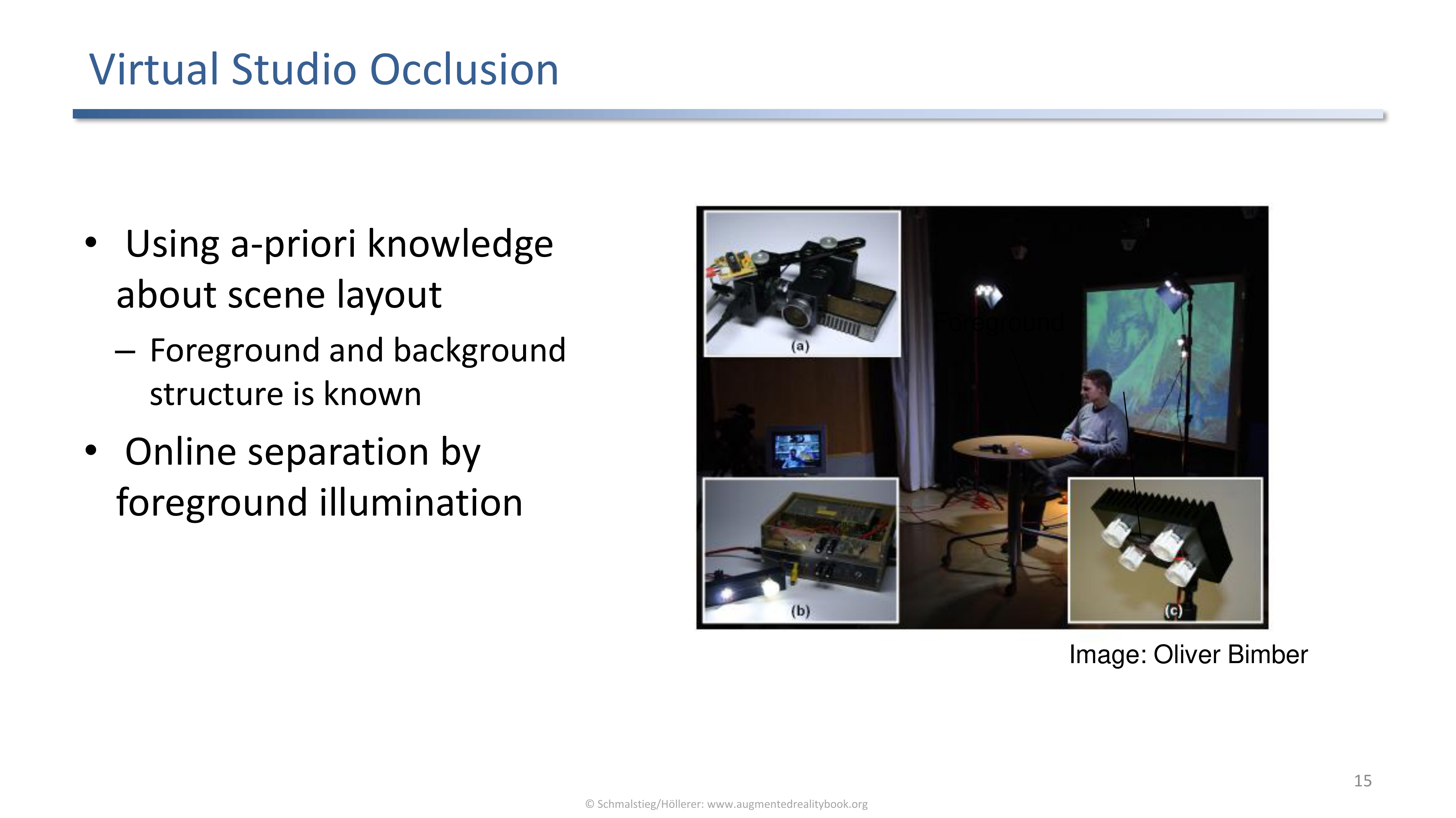
In a virtual studio the foreground and background structure is known in advance, so online separation can lean on structured light or foreground illumination.
The trick that broadcast studios use: tightly control the lighting and the set so foreground extraction is a solved problem.
Virtual Studio Example
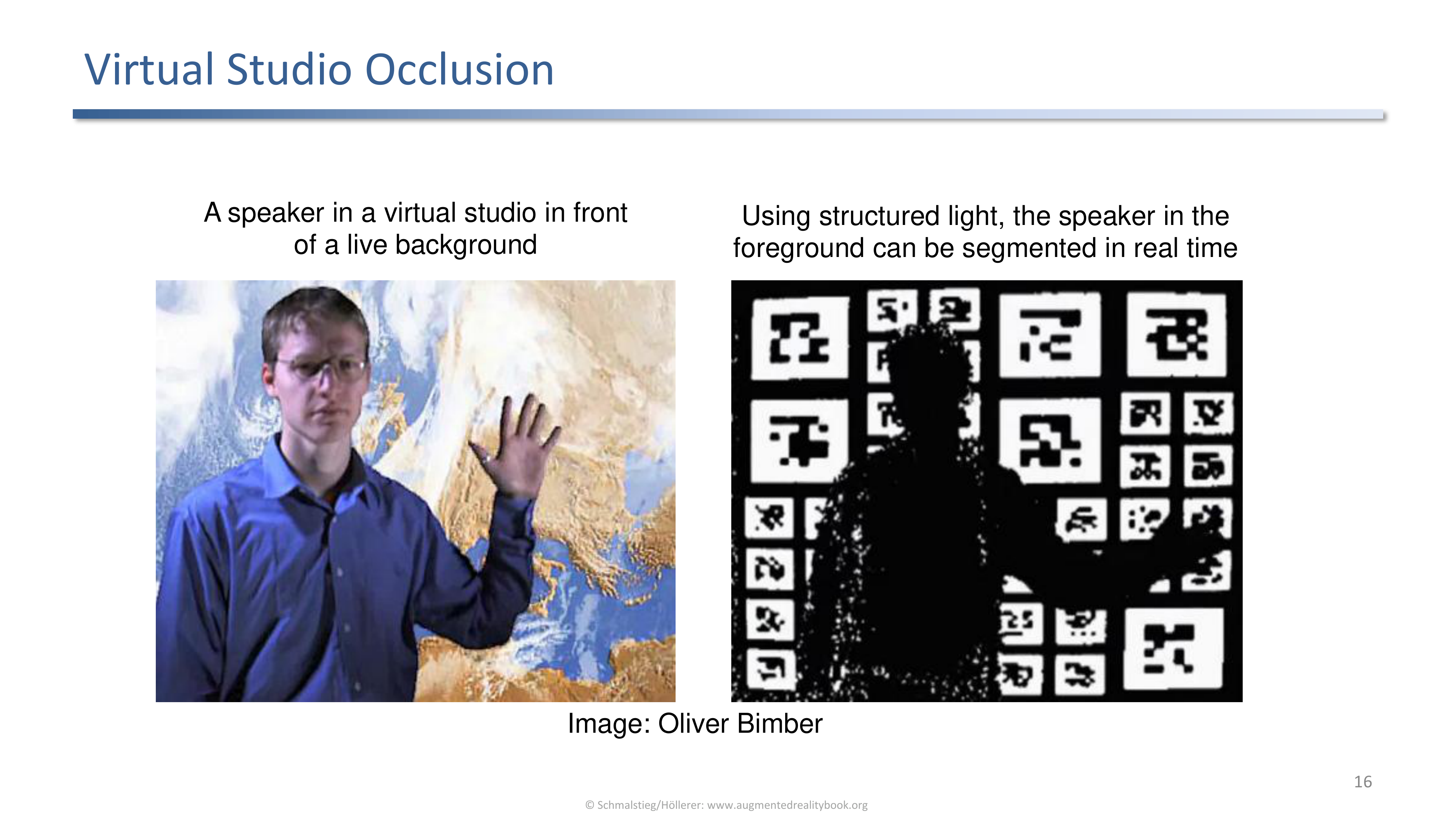
A speaker in front of a virtual background; structured light segments the speaker in real time so they remain in front of the compositing layer.
The same compositing pipeline as a film blue screen, but live and using structured light instead of chroma key.
BurnAR
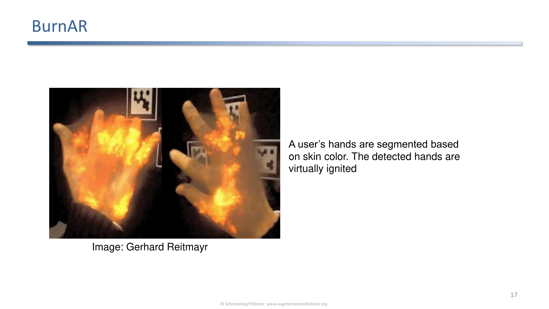
BurnAR segments the user's hands by skin color and virtually ignites them.
The detected hands are treated as a foreground mask so the fire effect lives in front of the rest of the scene without any explicit geometry.
Hand Occlusion
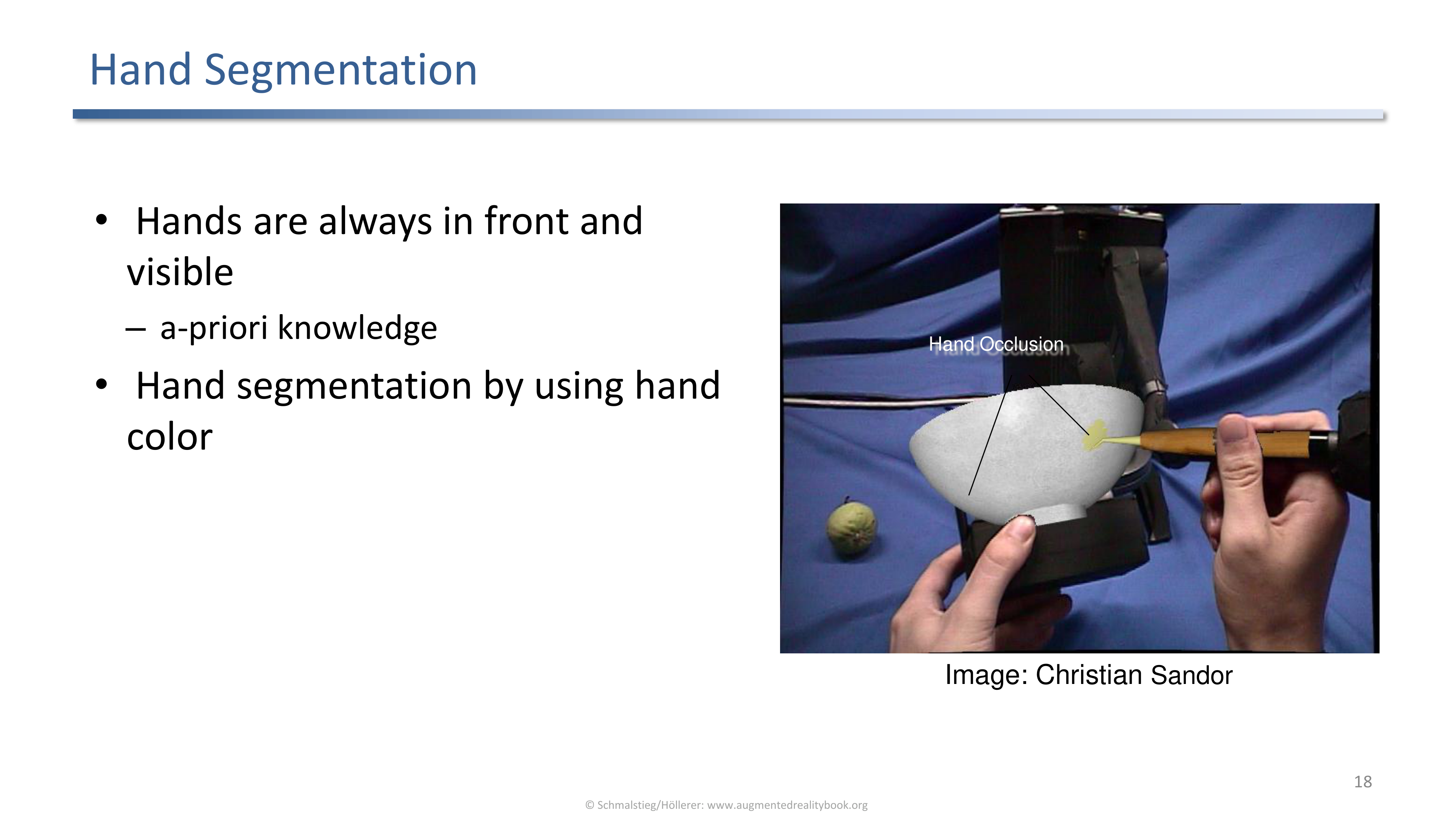
Hand occlusion uses the a-priori knowledge that hands are always in front and visible, plus skin color segmentation.
A pragmatic shortcut: do not try to recover hand geometry. Trust that the hands are nearest, segment by colour, and composite them on top.
3. Illumination
Light Interaction Between Virtual and Real
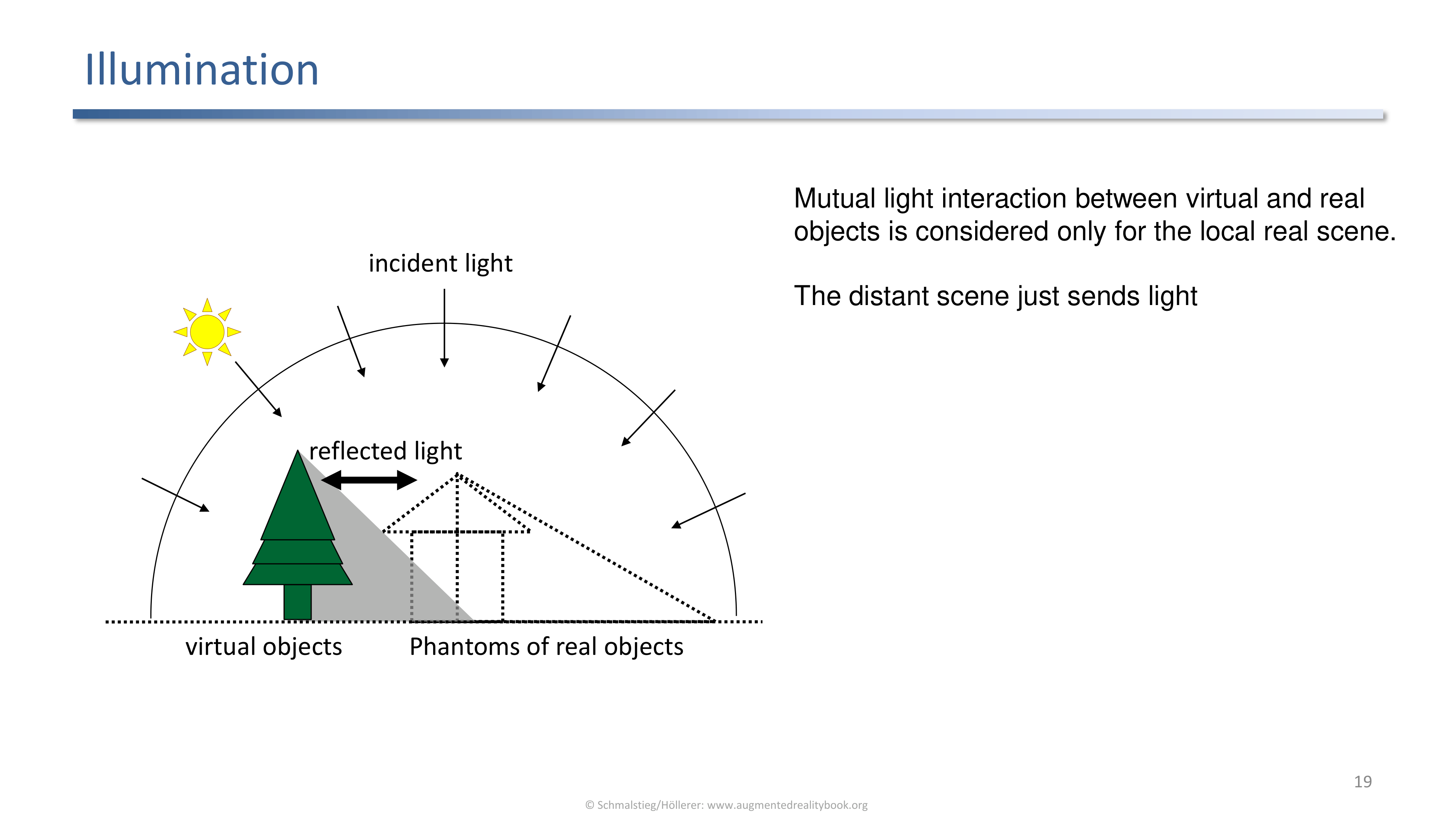
Mutual lighting is computed only for the local scene where phantoms exist. The distant scene contributes only as incoming light.
The local versus distant split keeps the cost manageable. Phantoms handle the bidirectional interaction with the virtual objects; everything farther away is approximated as an environment map of incoming light.
Environment Map
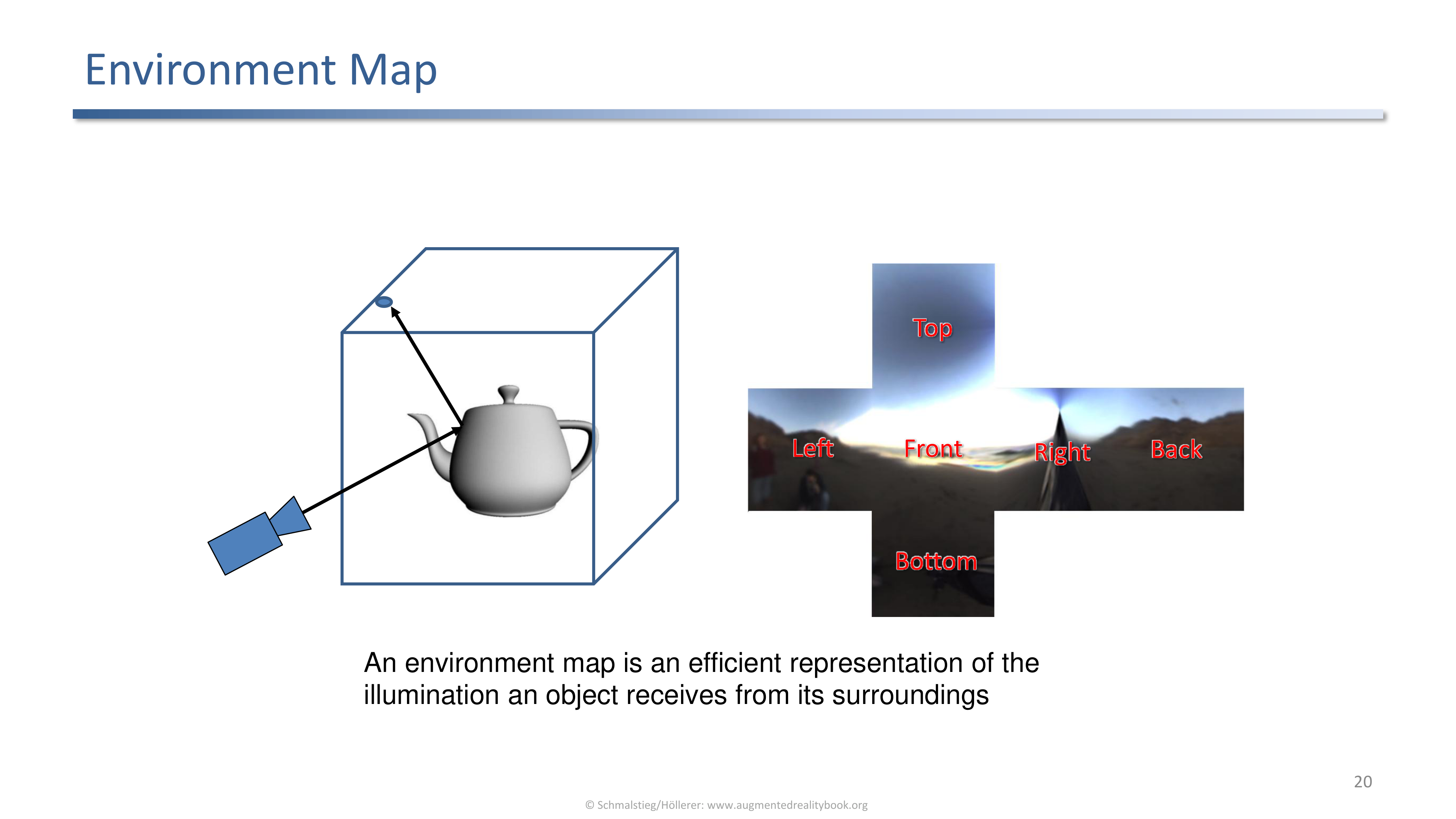
An environment map (cube map with front, left, right, back, top, bottom faces) compactly stores distant illumination.
The renderer samples the environment map for reflections and image-based lighting instead of integrating over a full light transport, which is what makes interactive performance possible.
Local vs Global Relighting
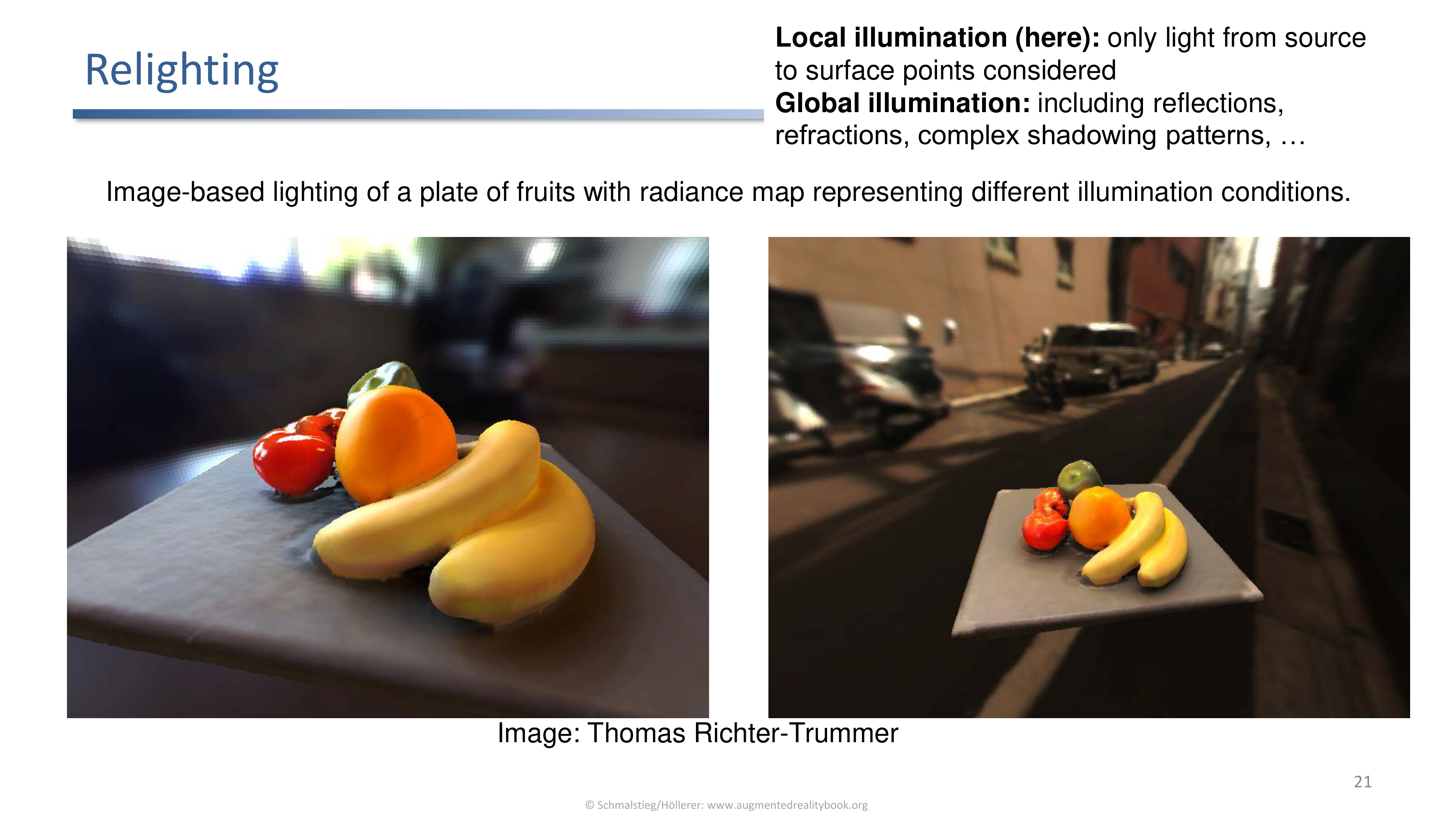
Image-based relighting of a plate of fruit under different radiance maps. Local illumination considers only source to surface; global illumination includes reflections, refractions, and complex shadows.
The qualitative jump from local to global is what makes integrated virtual objects look photographic. The cost is also where most of the budget goes.
Illumination Reconstruction
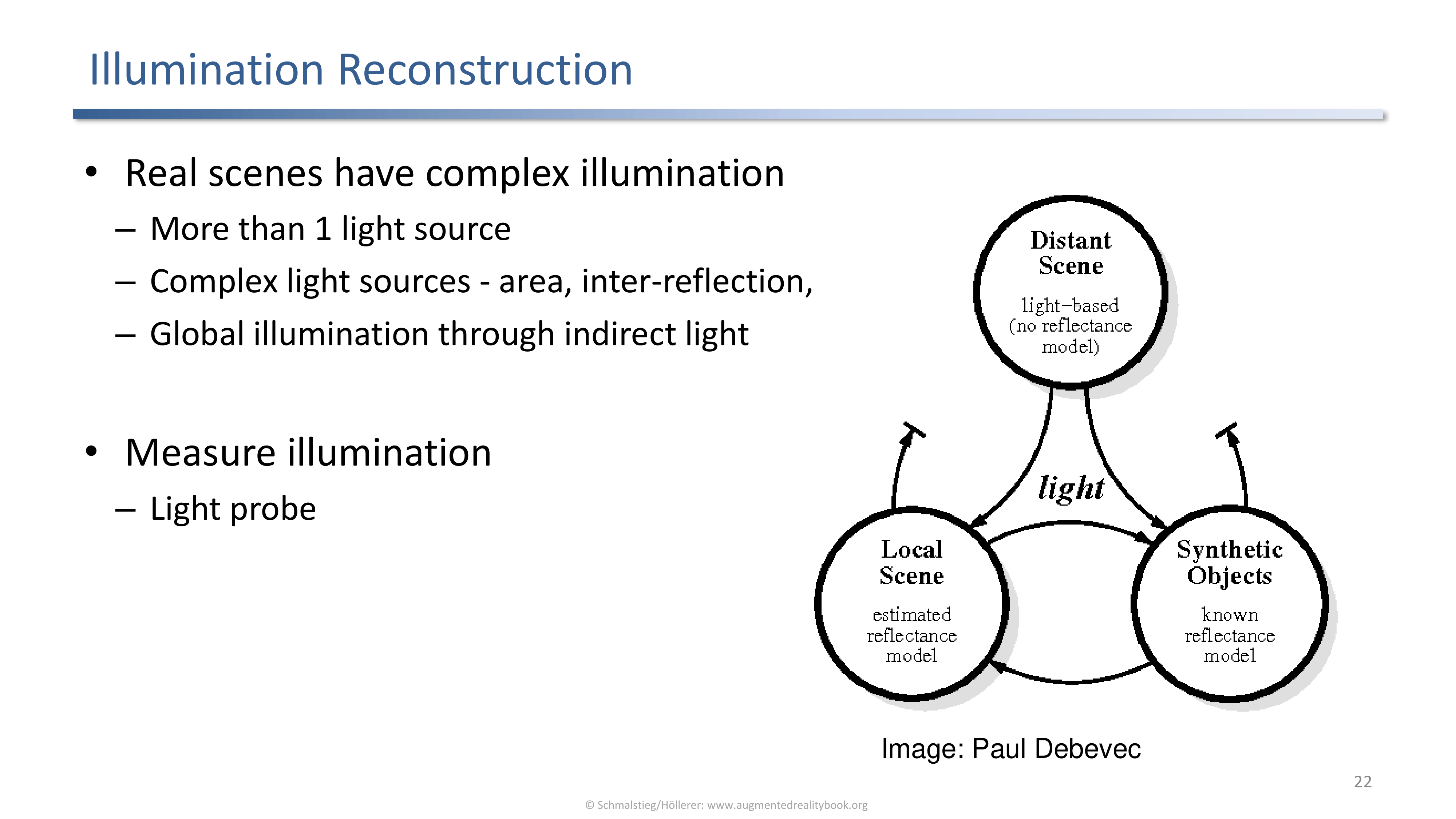
Real scenes have multiple sources, area sources, inter-reflection, color, and indirect light. The system has to measure all of that, typically with a light probe.
Reconstructing illumination boils down to estimating an environment map for the scene, however coarsely.
Light Probes
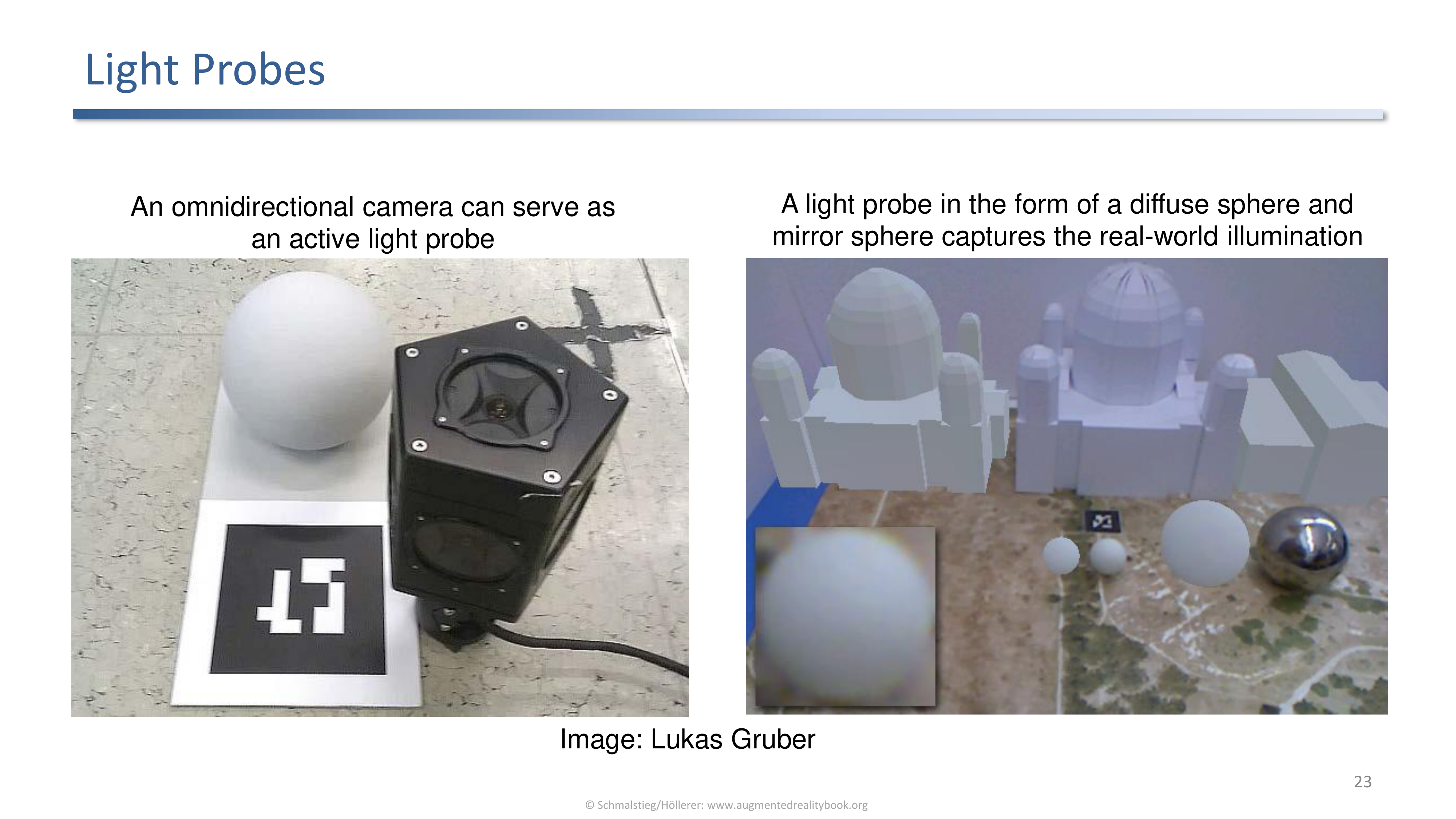
A light probe captures the surrounding light: an omnidirectional camera, or the classic diffuse plus mirror sphere pair.
The probe sits in the scene during capture so the captured directions correspond to the eventual rendering positions.
Light Probes and Environment Maps
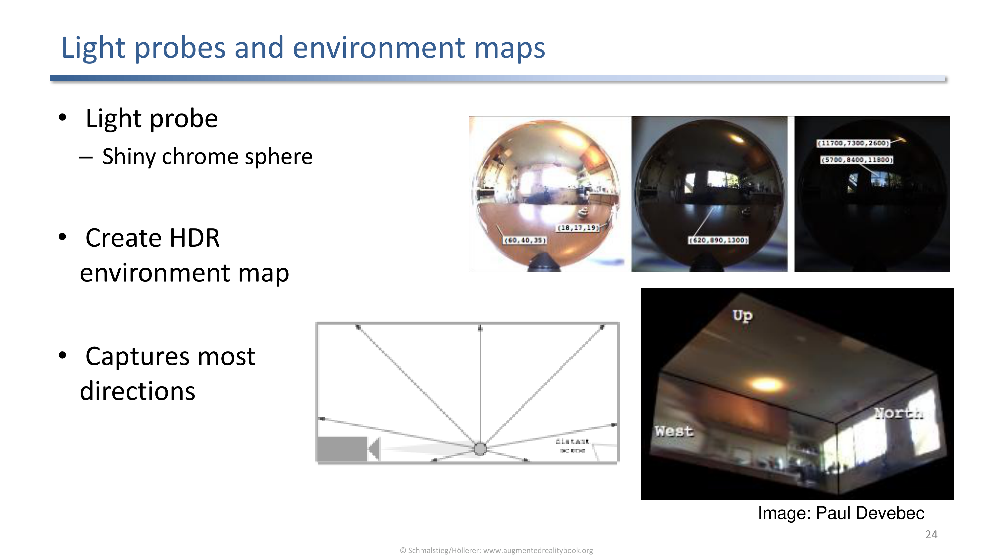
A shiny chrome sphere creates an HDR environment map that captures most directions. HDR is needed because real light sources are several orders of magnitude brighter than the rest of the scene.
The HDR step is what lets the same map drive both subtle diffuse shading and bright specular highlights without clipping.
Textured Target as Light Probe
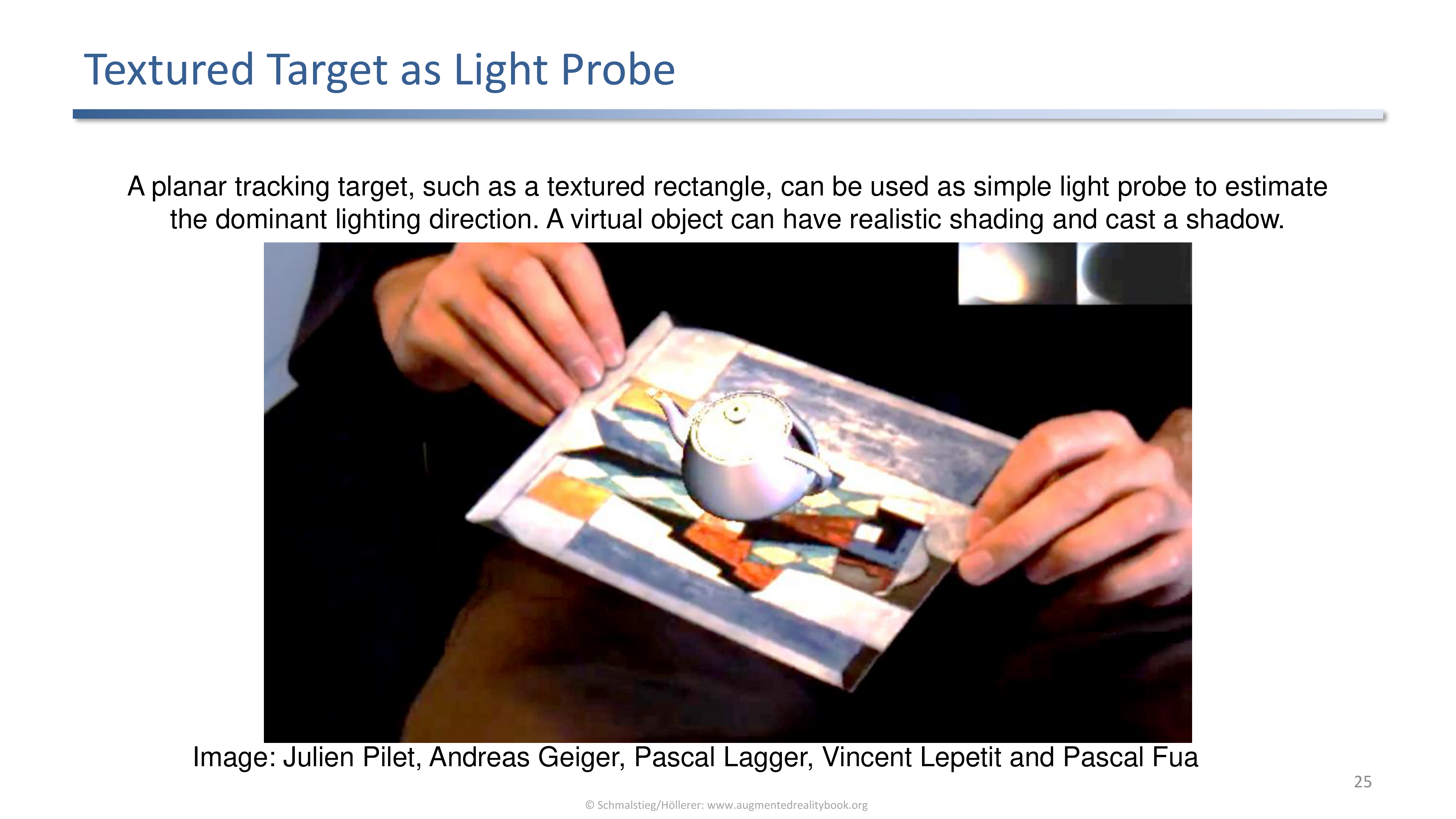
A planar textured target doubles as a light probe by estimating the dominant lighting direction, enough to shade a virtual object and cast a shadow.
When carrying around a chrome sphere is not practical, an existing tracking target can give a coarse but usable estimate.
Photometric Registration
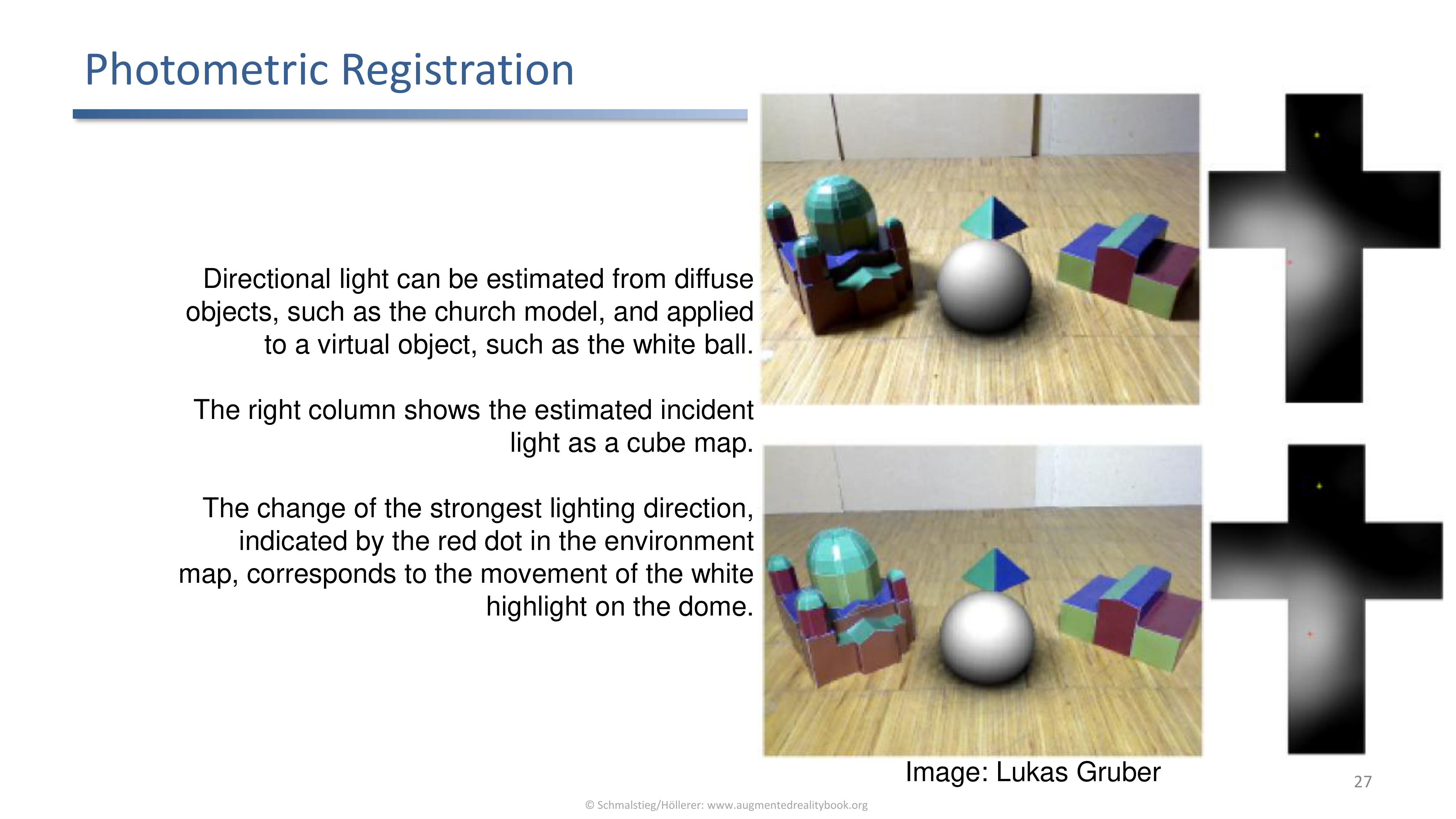
Directional light estimated from a diffuse object (here a church model) is applied to a virtual ball. The right column shows the estimated incident light as a cube map with the dominant direction marked.
Photometric registration aligns lighting between the virtual and the real, the way geometric registration aligns position.
Learning Lightprobes for Mixed Reality
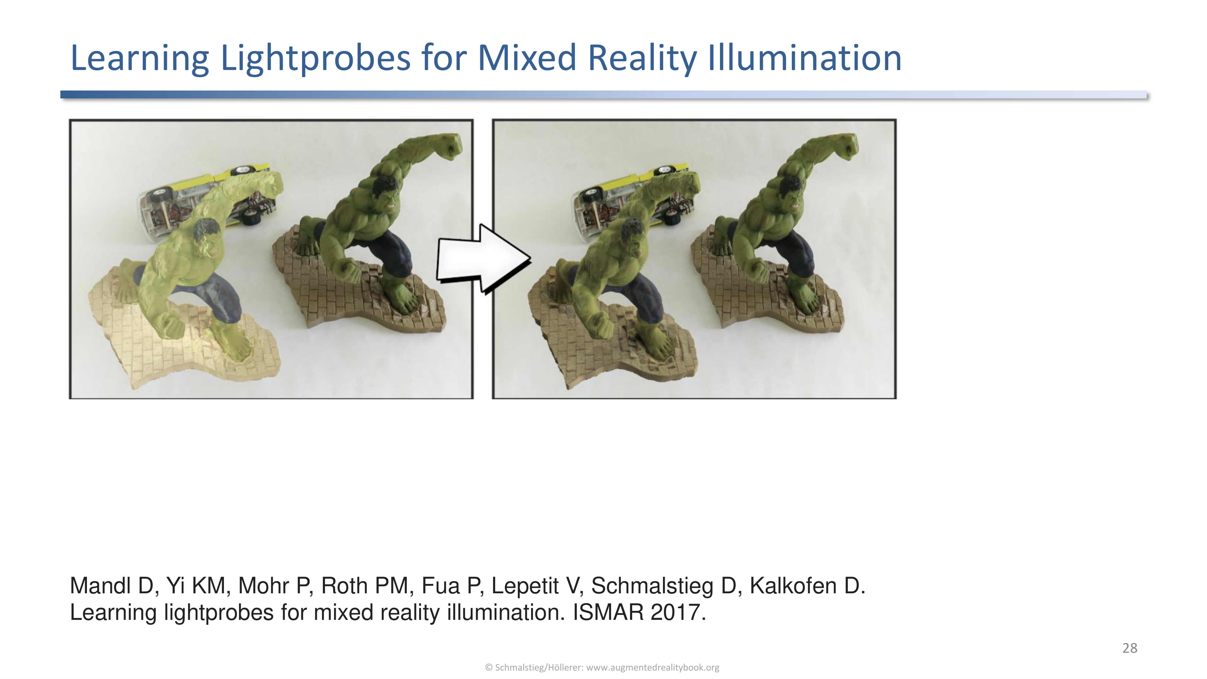
A learned model predicts an environment map directly from a single image (Mandl et al., ISMAR 2017), removing the need for a physical light probe at runtime.
Once a model is trained, the runtime cost drops to a forward pass, which is what makes this approach practical on a headset.
Using Shadows to Find a Light Source
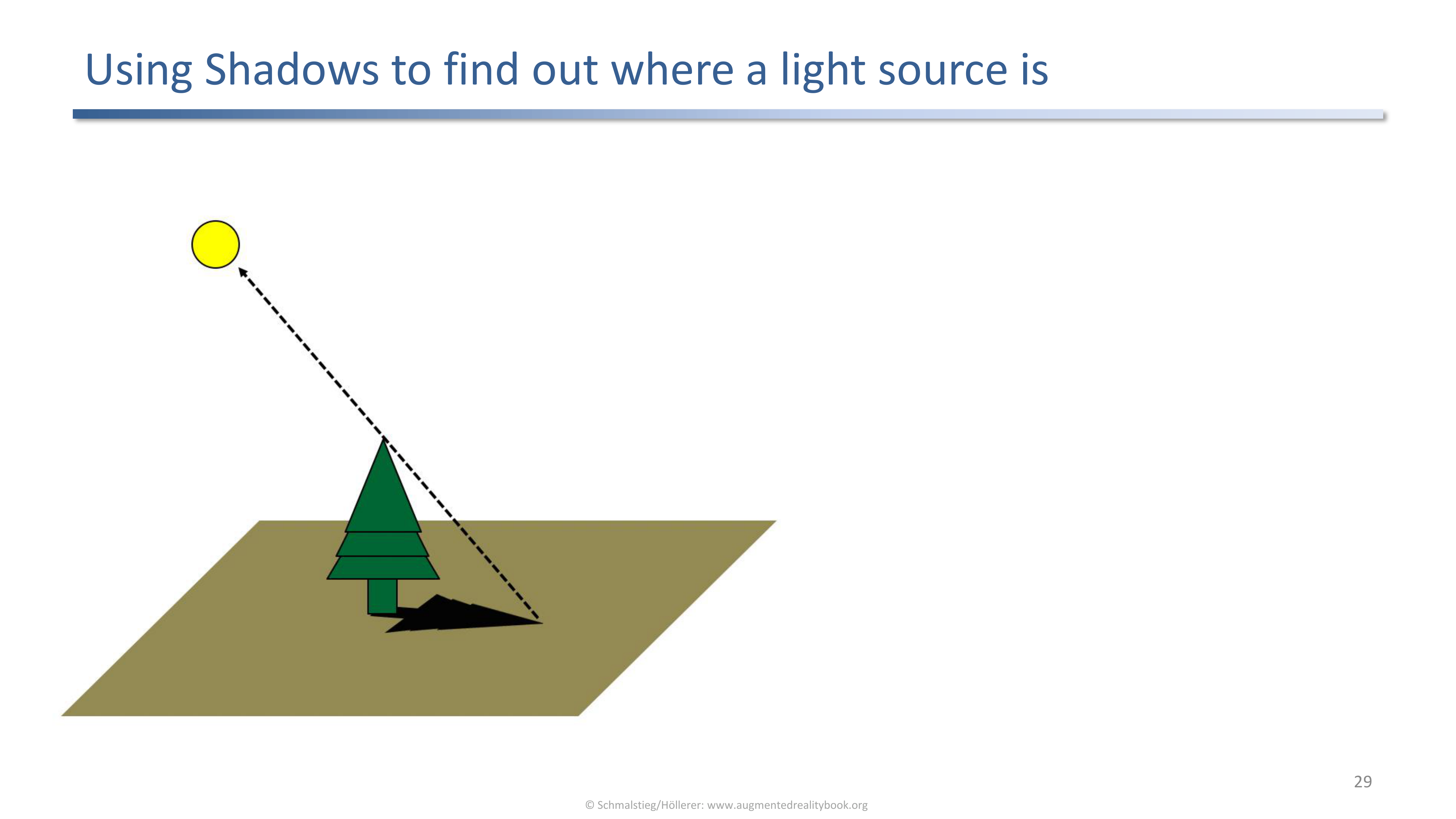
Existing shadows in the video reveal where the real light source is, which then drives both shading and shadow casting for the virtual object.
Inverting from observed shadows to a light direction is the photometric inverse problem of shadow casting. It is cheap and works whenever the scene already has prominent shadows.
4. Shadows
Why Shadows Matter
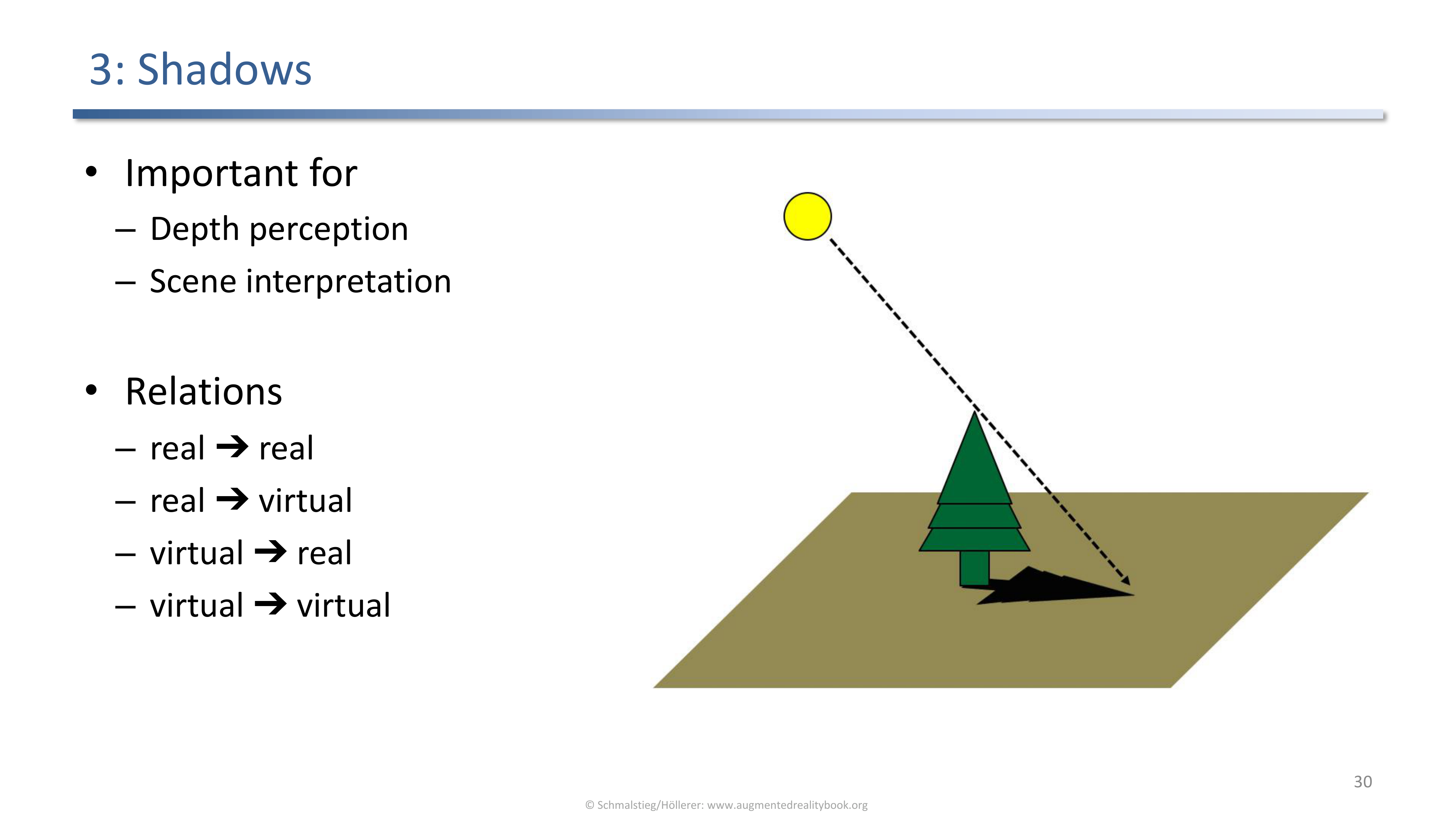
Shadows give depth and scene interpretation. Four relations need to be handled: real to real, real to virtual, virtual to real, and virtual to virtual.
The four relations are not symmetric in cost or in importance. Virtual-to-real shadows are visually critical (they ground virtual objects on the real floor) while real-to-real shadows are already in the video.
Drop Shadow on a Plane
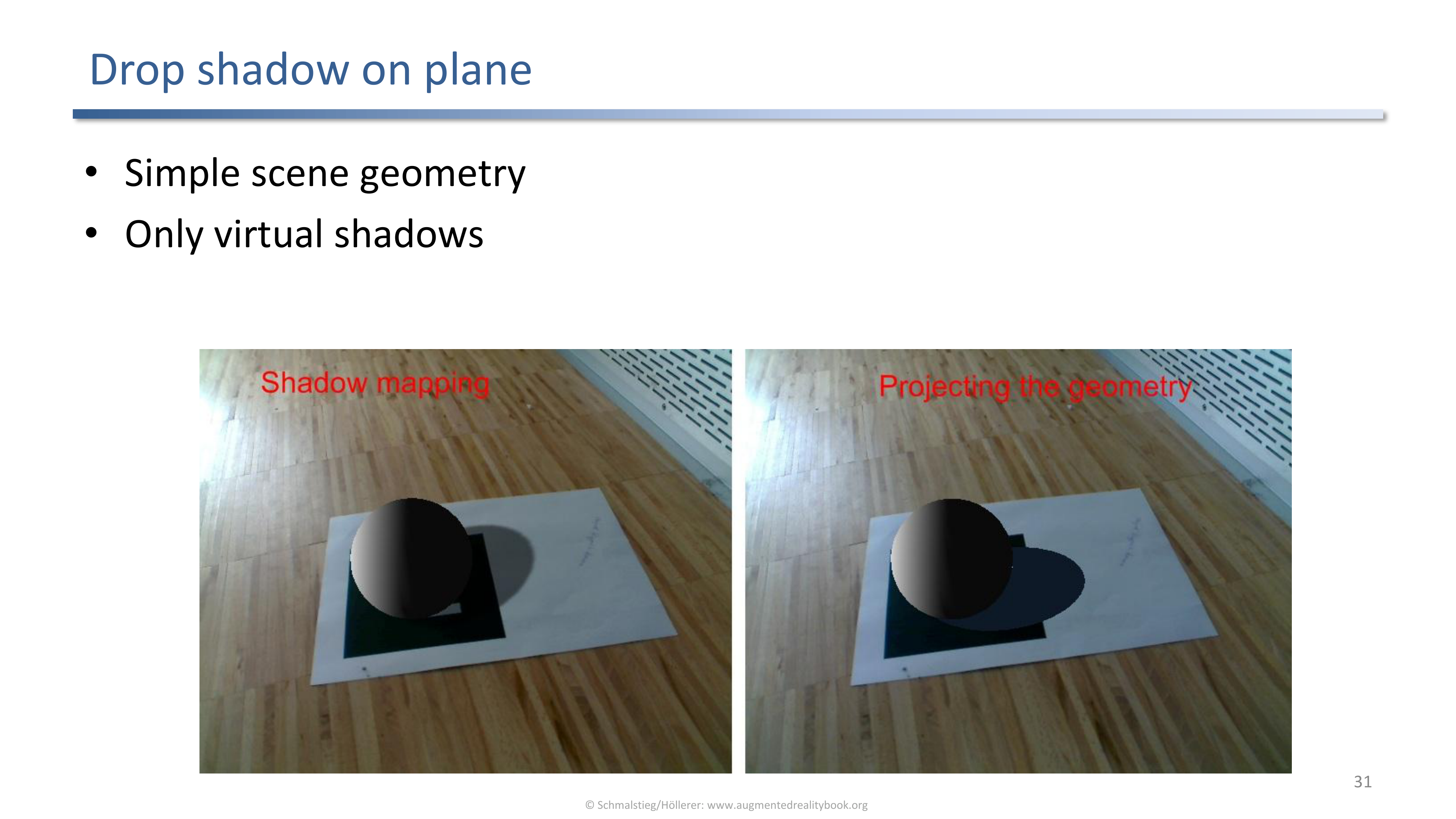
Simplest geometry: assume a ground plane and drop a virtual shadow onto it.
A cheap trick that already buys a lot of perceived realism. Many mobile AR demos stop here.
Scene Model Requirements
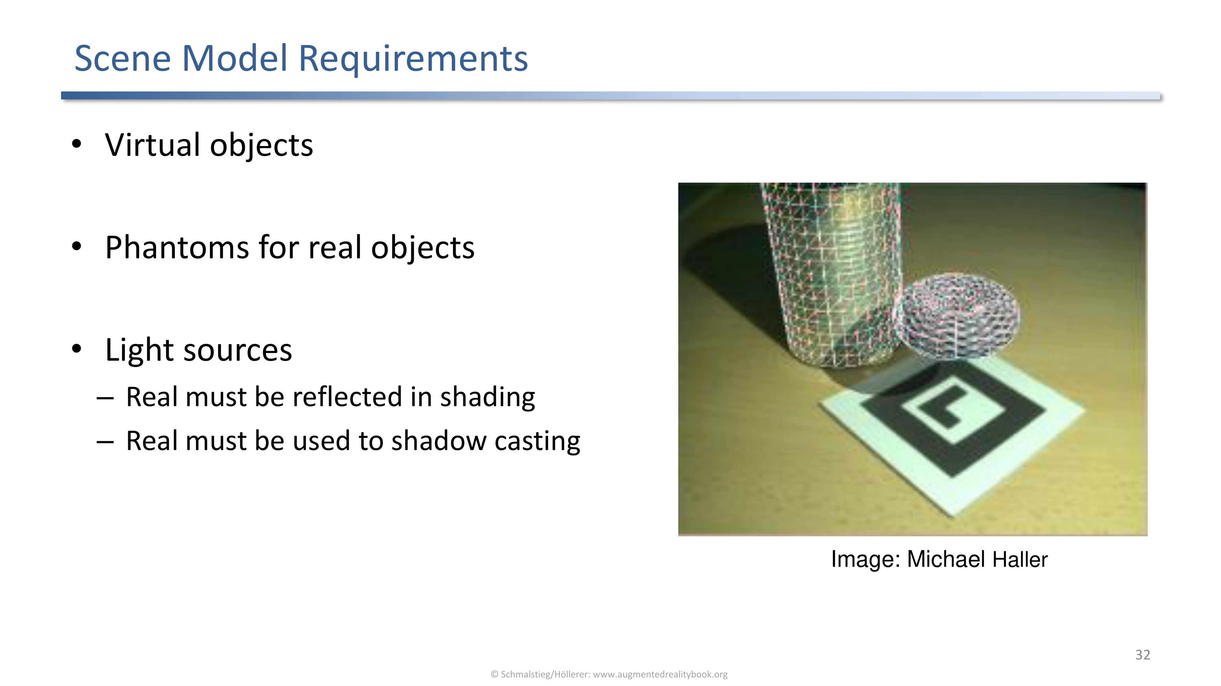
For correct shadows the scene model needs virtual objects, phantoms for real objects, and the light sources. Real lights must be reflected in shading and used for shadow casting.
Notice that the light source becomes a first-class object in the scene representation, not just an environment map.
Shadow Volumes
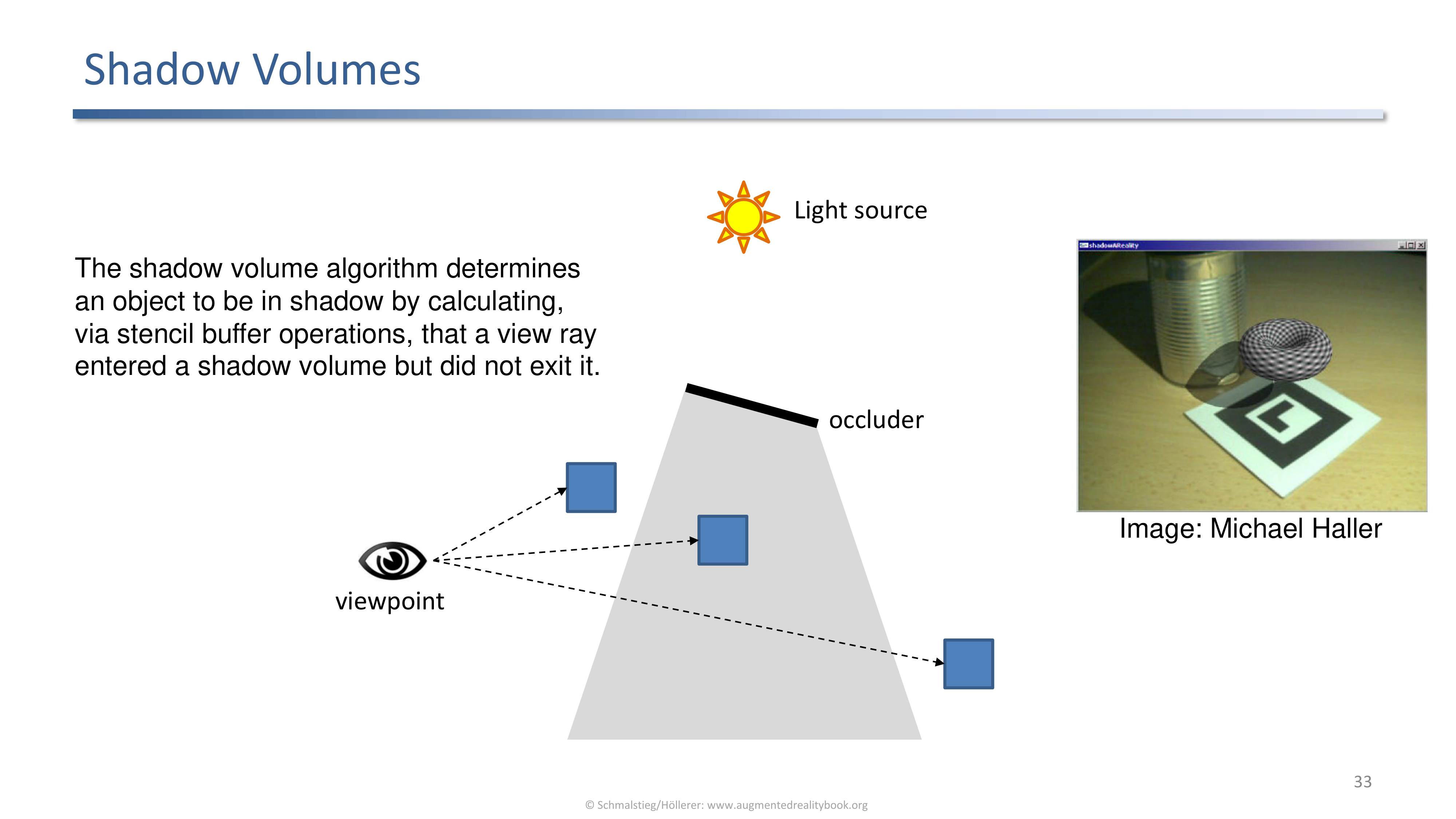
Shadow volume algorithm: a view ray that enters a shadow volume without exiting it ends inside the shadow, counted by stencil buffer operations.
Standard real-time graphics technique, reused here for AR with one extra step.
AR Shadow Volumes
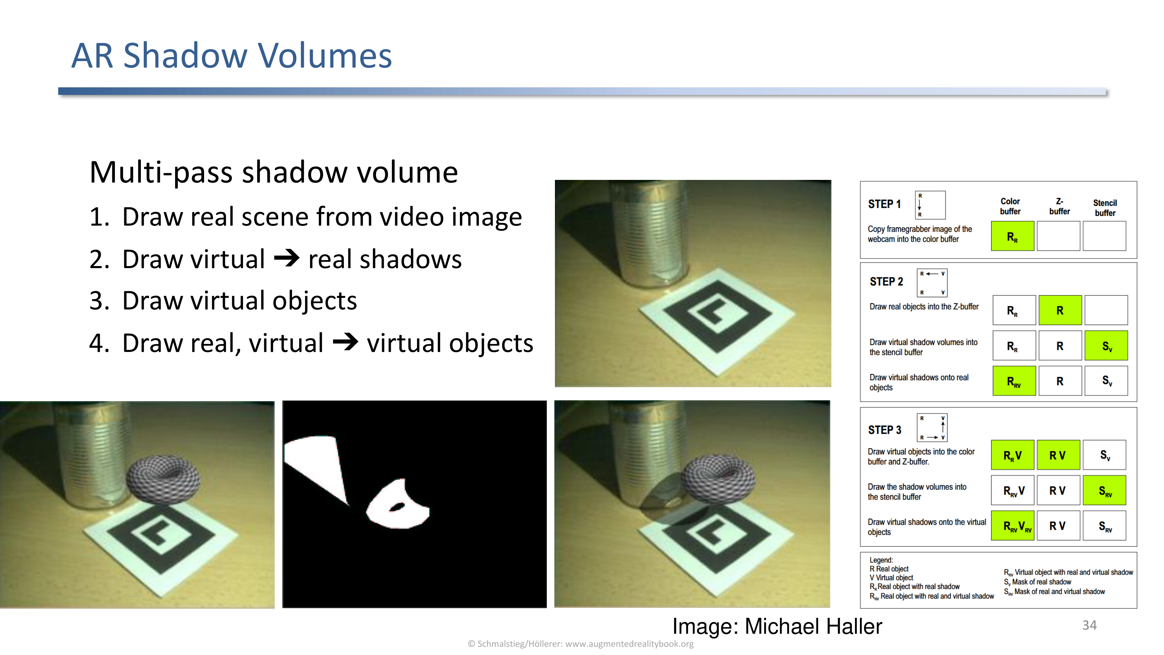
Multi-pass shadow volume pipeline for AR: video, virtual to real shadows, virtual objects, then real, virtual to virtual.
The four-pass structure:
- Draw the real scene from the video image.
- Draw the virtual-to-real shadows on top of the video.
- Draw the virtual objects.
- Draw real-to-virtual and virtual-to-virtual shadows.
Differential Rendering
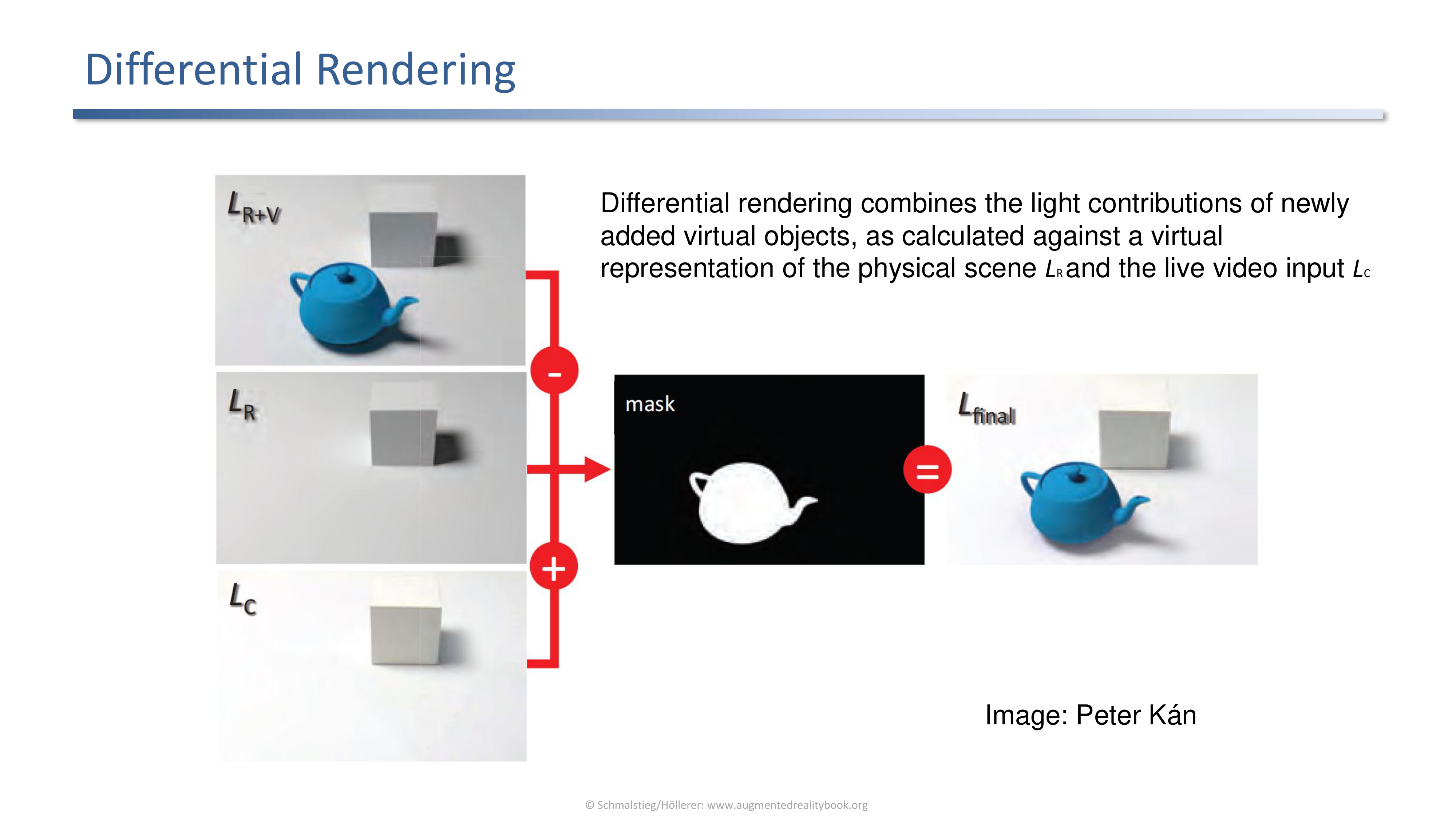
Differential rendering combines new virtual contributions (computed against a phantom scene `LR`) with the live video input `LC`.
Concretely: render the scene with the virtual object, render it again without, take the difference, and add that difference to the captured video. The difference carries the new shadows and indirect light without disturbing the rest of the image.
Differential Rendering Results
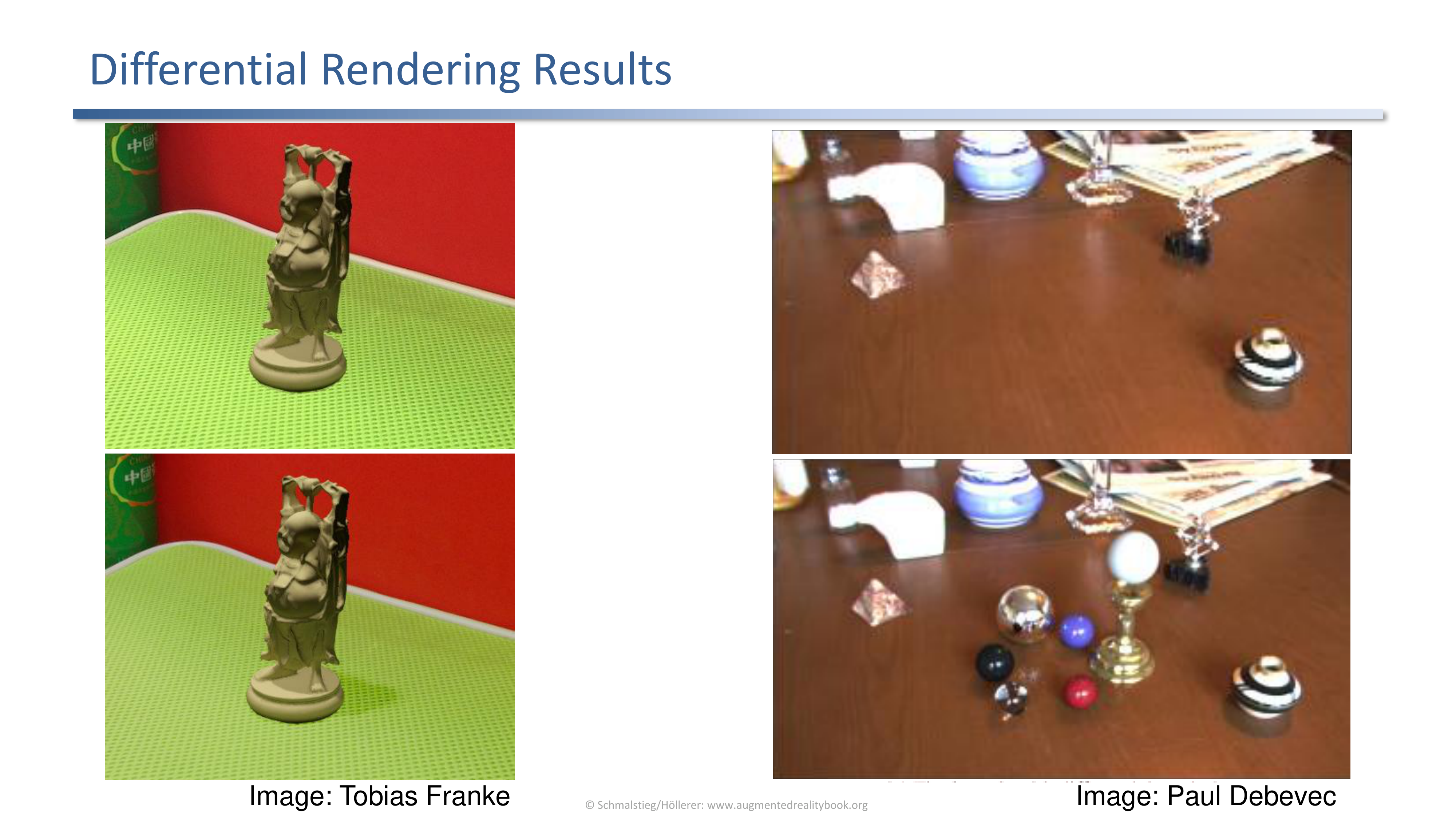
Debevec and Franke show differential rendering integrating a virtual object into a captured environment with consistent indirect lighting and shadows.
Even with a coarse phantom of the scene the result looks plausible because all the indirect effects are differences against the same captured background.
Differential Path Tracing
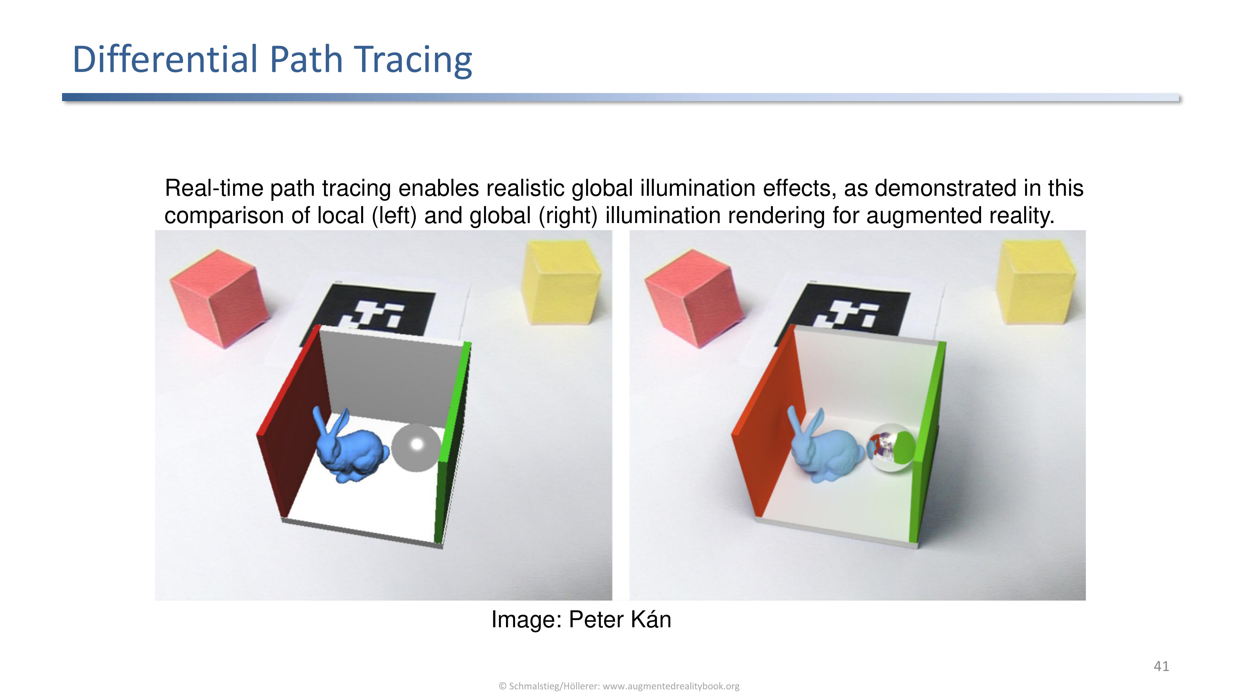
Real-time path tracing pushes differential rendering into global illumination. Side-by-side comparison of local (left) and global (right) illumination for AR.
The same differential principle, but with a physically-based light transport that captures multi-bounce effects.
Differential Photon Mapping
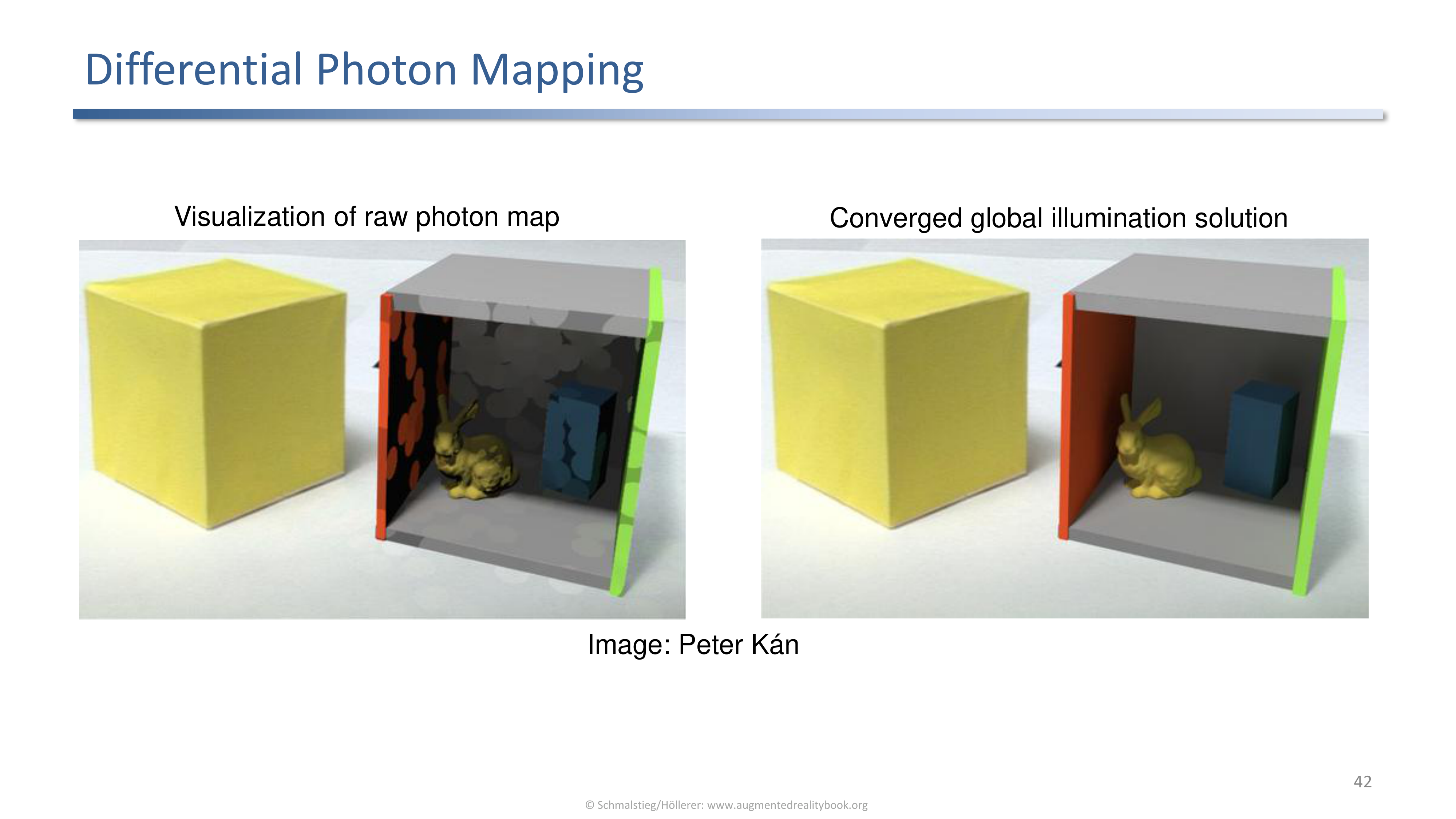
Differential photon mapping (Kán) is another route to global illumination. Visualization of the raw photon map next to the converged solution.
Photon mapping is well suited for caustics and indirect light through transparent objects, which complements path tracing’s strengths.
Double Shadowing
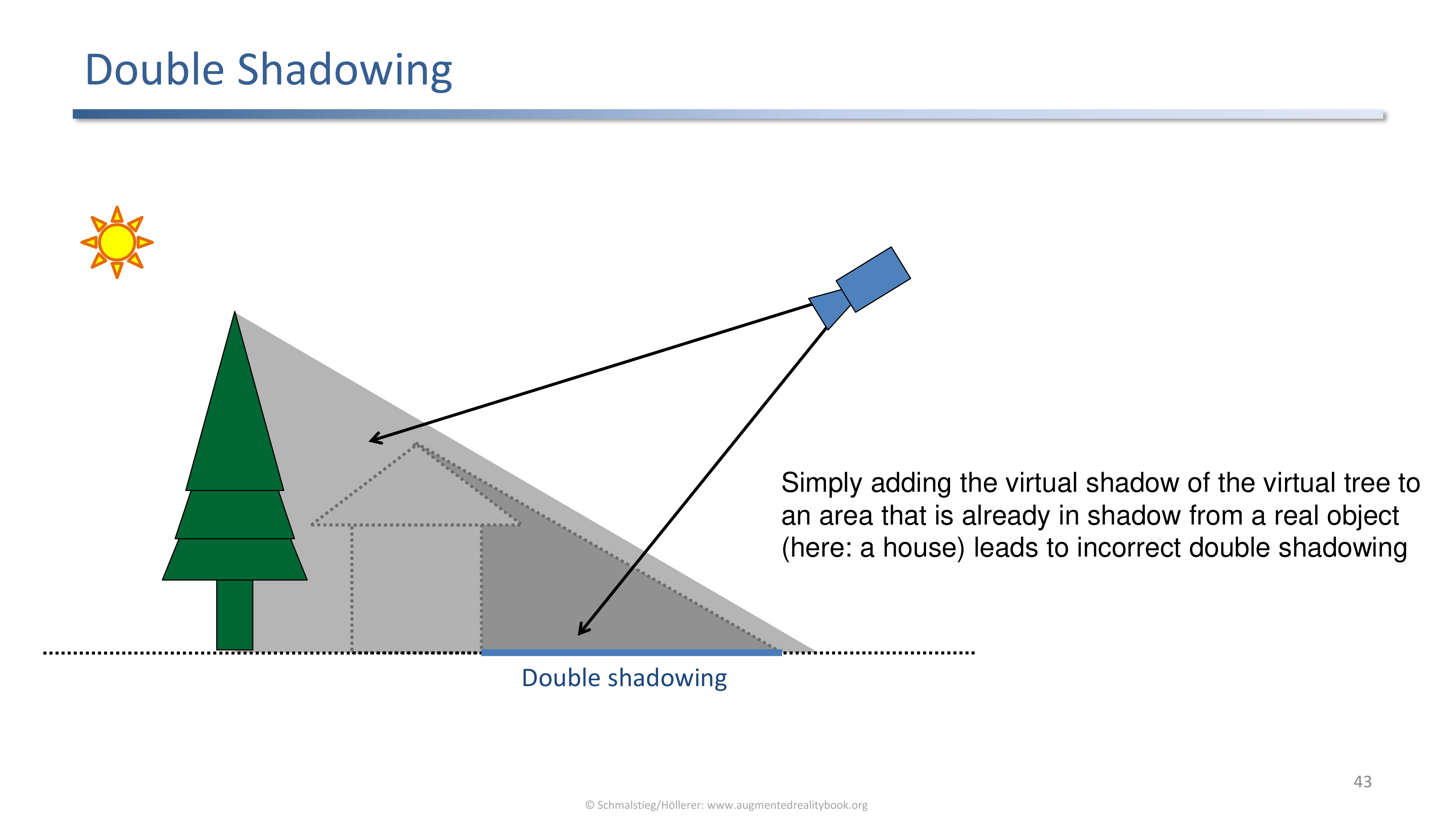
Adding a virtual shadow over an area already in shadow from a real object yields incorrect double shadowing (a virtual tree's shadow added on top of a real house's shadow).
A failure mode of naive shadow compositing. The fix is either differential rendering (which subtracts the duplicated darkening) or explicit reasoning about which regions are already in shadow.
5. Reflections and Refractions
Reflections
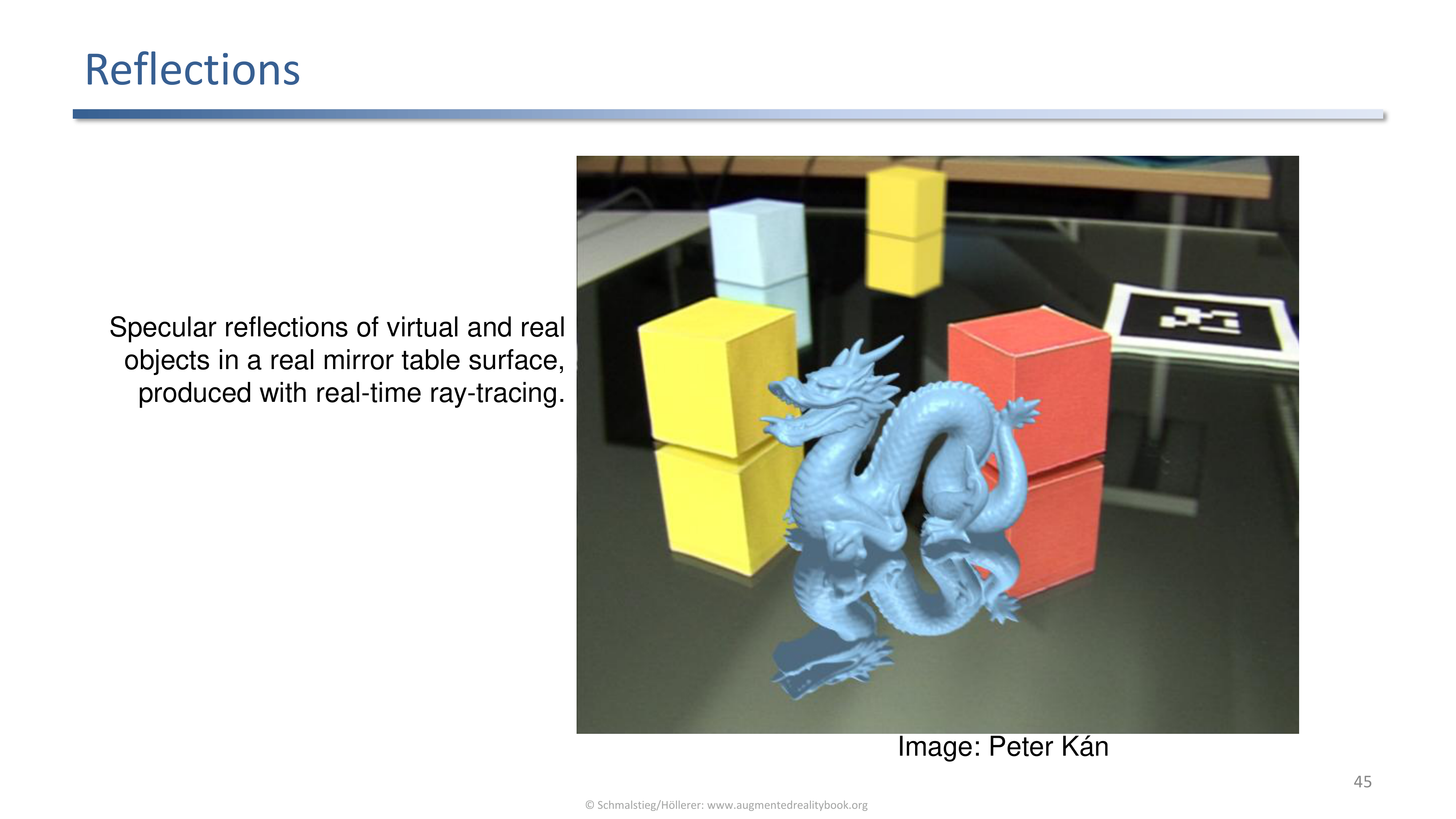
Specular reflections of virtual and real objects on a real mirror surface produced with real-time ray tracing (Kán).
For mirror surfaces both kinds of objects need to appear in the reflection. Real-time ray tracing is the cleanest way to handle this once the GPU can sustain it.
Refractions
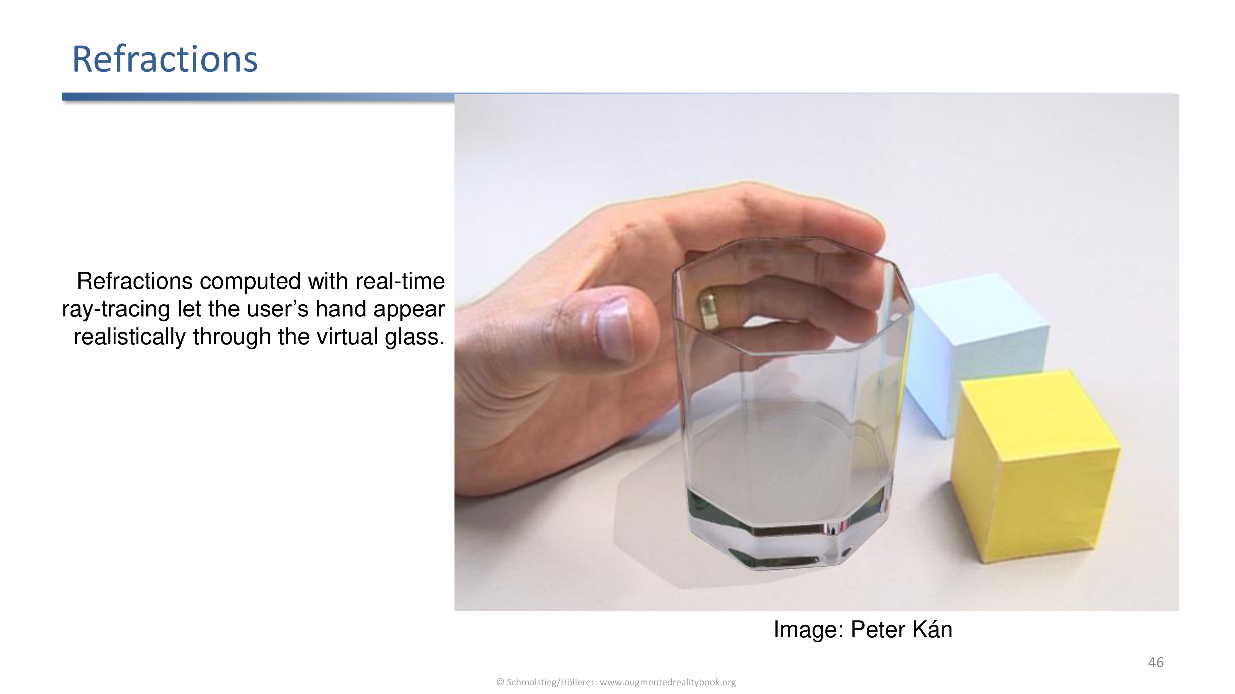
Real-time ray-traced refractions through a virtual transparent object: the user's real hand appears realistically behind the virtual glass.
The same ray-traced pipeline handles transmission. The illusion only holds if the index of refraction and the geometry of the virtual object match what the eye expects.
6. Visual Special Effects
Diminished Reality and Stylization
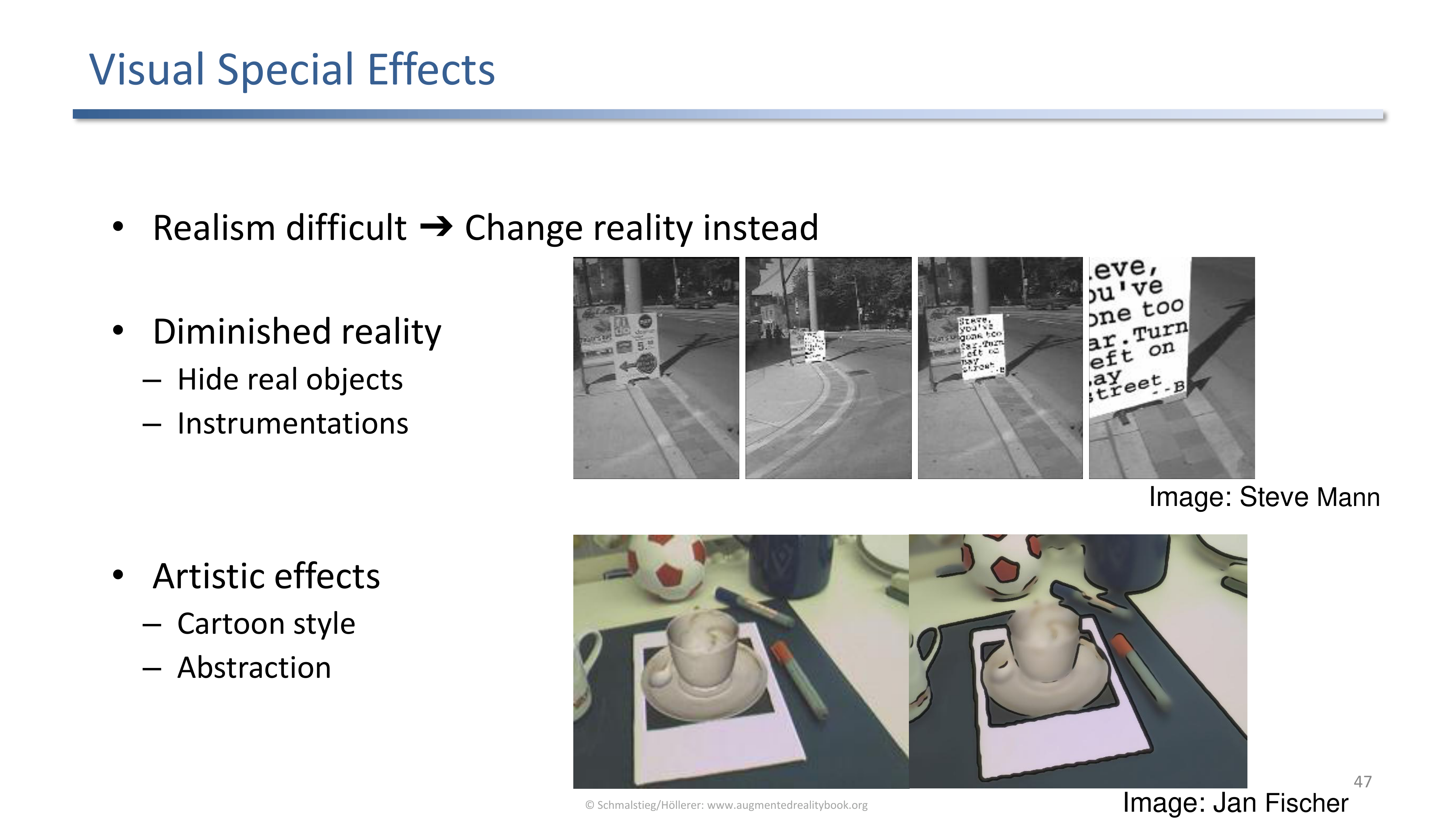
Photorealism is hard, so an alternative is to deliberately change reality: hide objects (diminished reality) or use a non-photorealistic style for both halves.
Both branches sidestep the realism problem instead of solving it. Diminished reality removes the things that would clash; stylization makes everything clash uniformly so the eye stops trying to compare to reality.
Diminished Reality
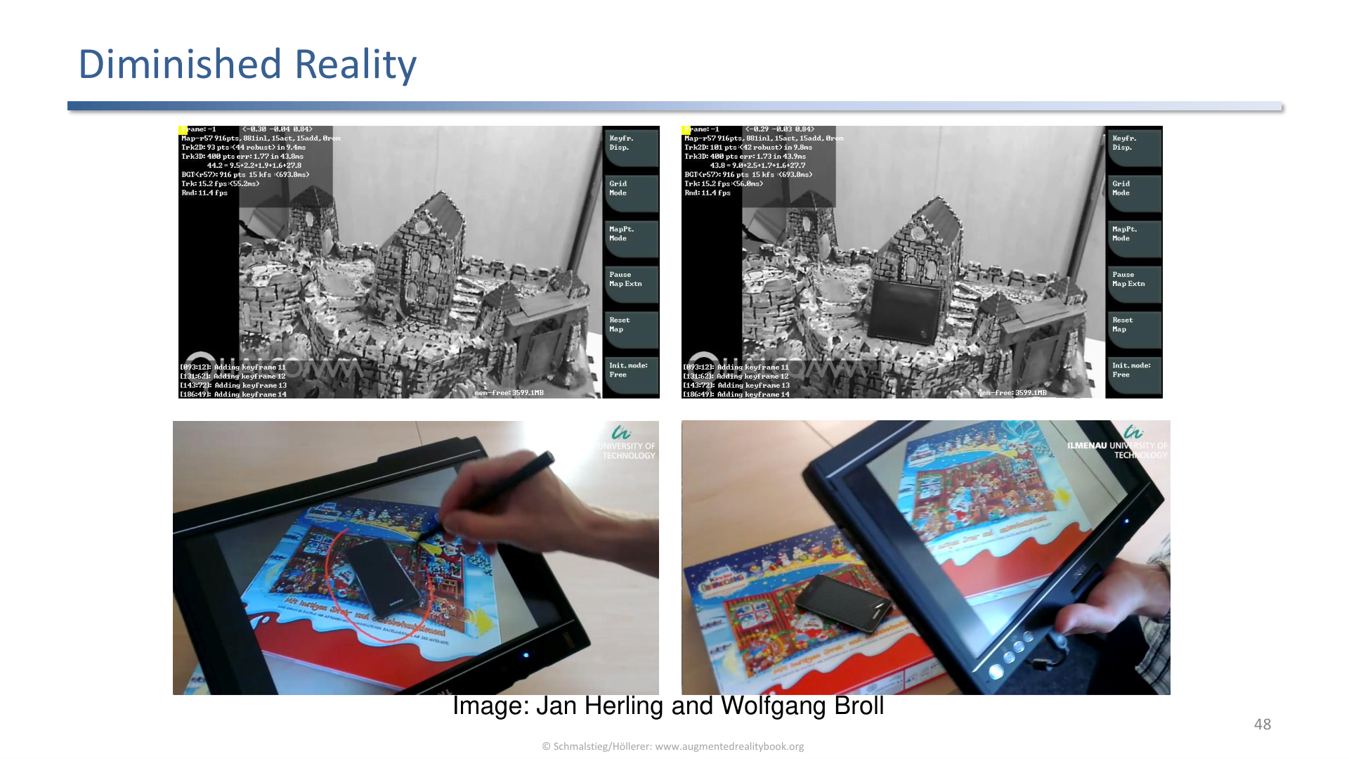
Diminished reality removes real objects from the scene by filling in plausible background content (Herling and Broll).
The system identifies the object to remove, masks it out, and inpaints from the surrounding pixels so the seam is invisible.
Diminished Reality for Marker Removal
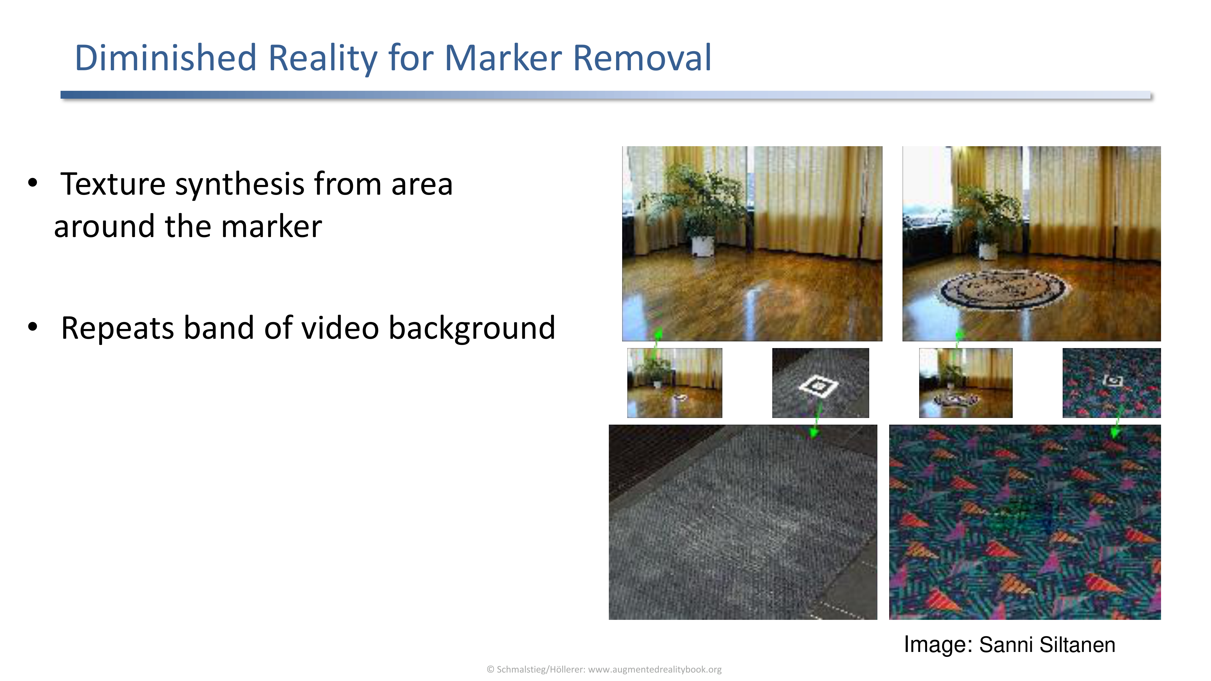
Texture synthesis around a fiducial marker repeats a band of video background over the marker so it disappears from the final image.
A common practical case: the tracking system needs the marker, but the user should not see it. Texture synthesis is enough when the surrounding texture is repetitive.
Diminishing a Haptic Device
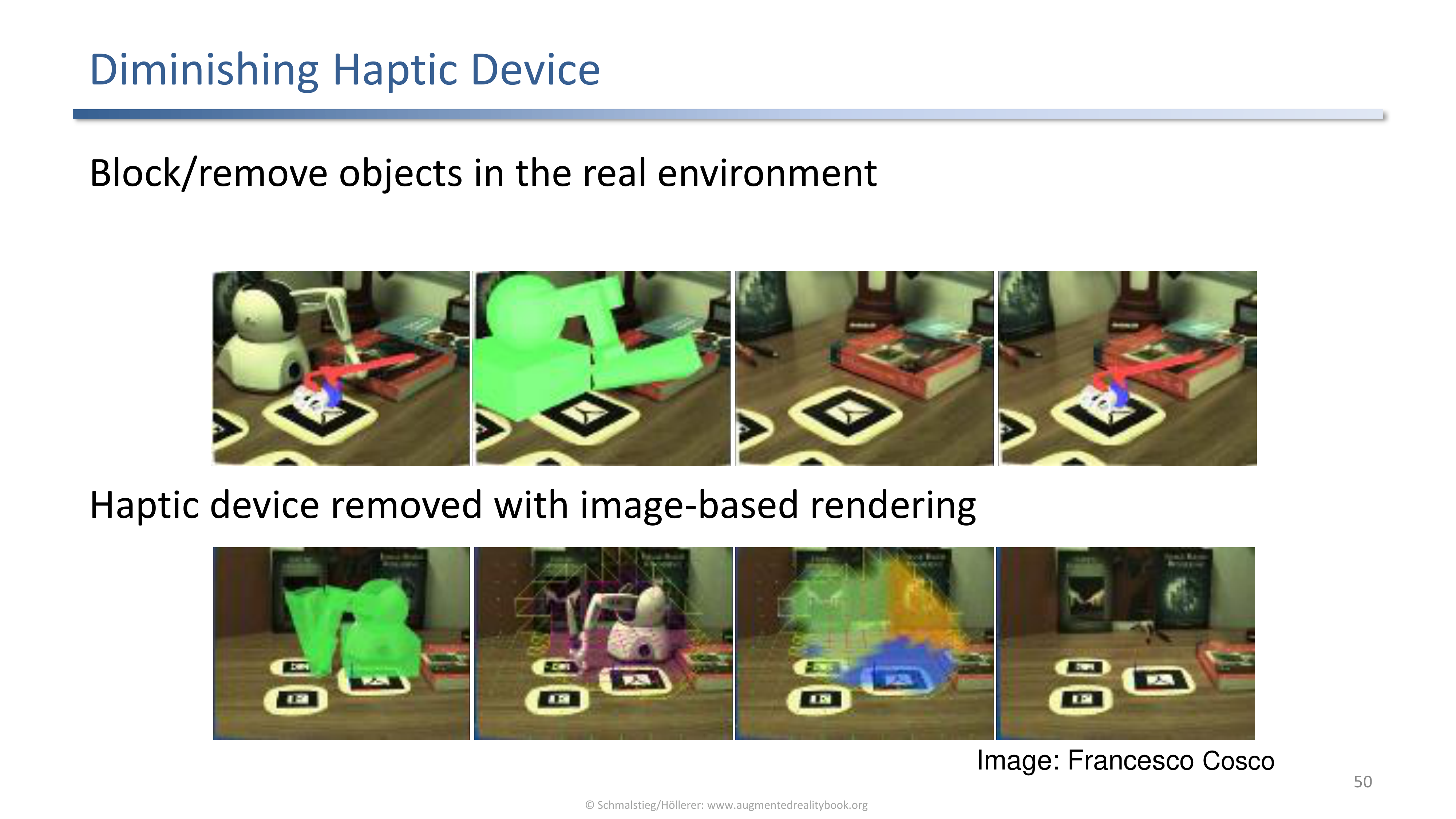
A haptic device removed from the user's view with image-based rendering, leaving the impression of unmediated interaction.
Removes the rig so the user perceives only the interaction with the virtual content.
PixMix Examples
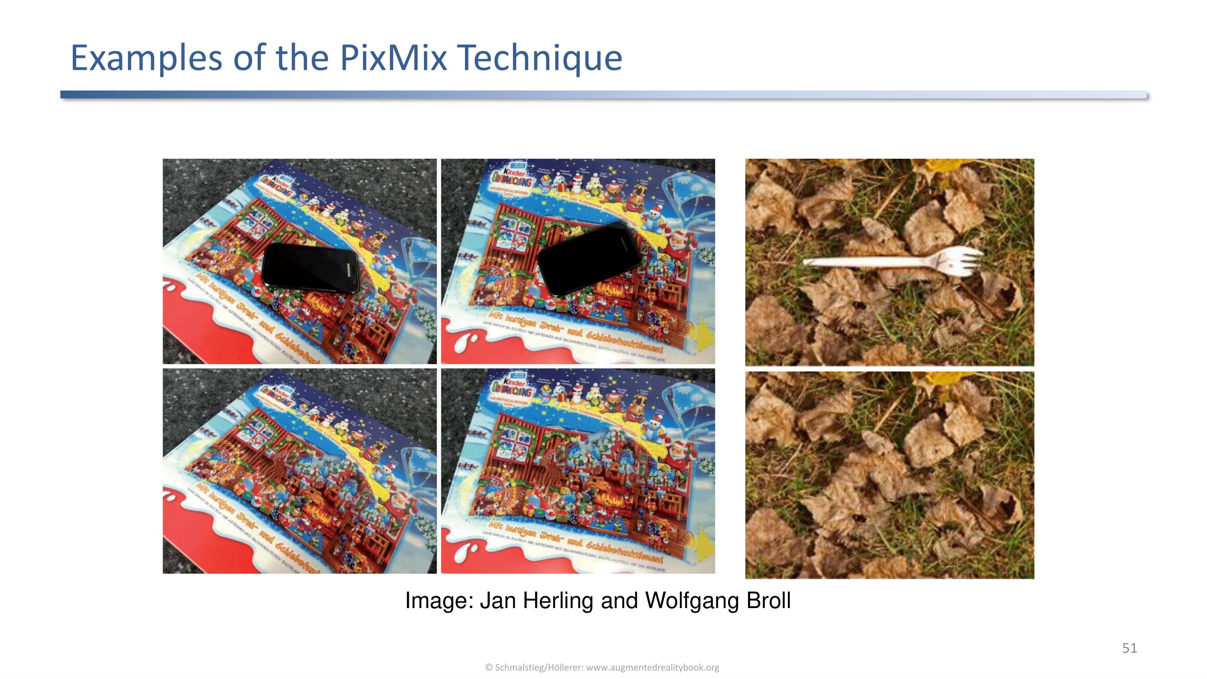
PixMix (Herling and Broll) removes chosen objects from cluttered real scenes without leaving obvious holes.
A more general inpainting technique that holds up on textured backgrounds where simple band-repetition fails.
Projector-Based Diminished Reality
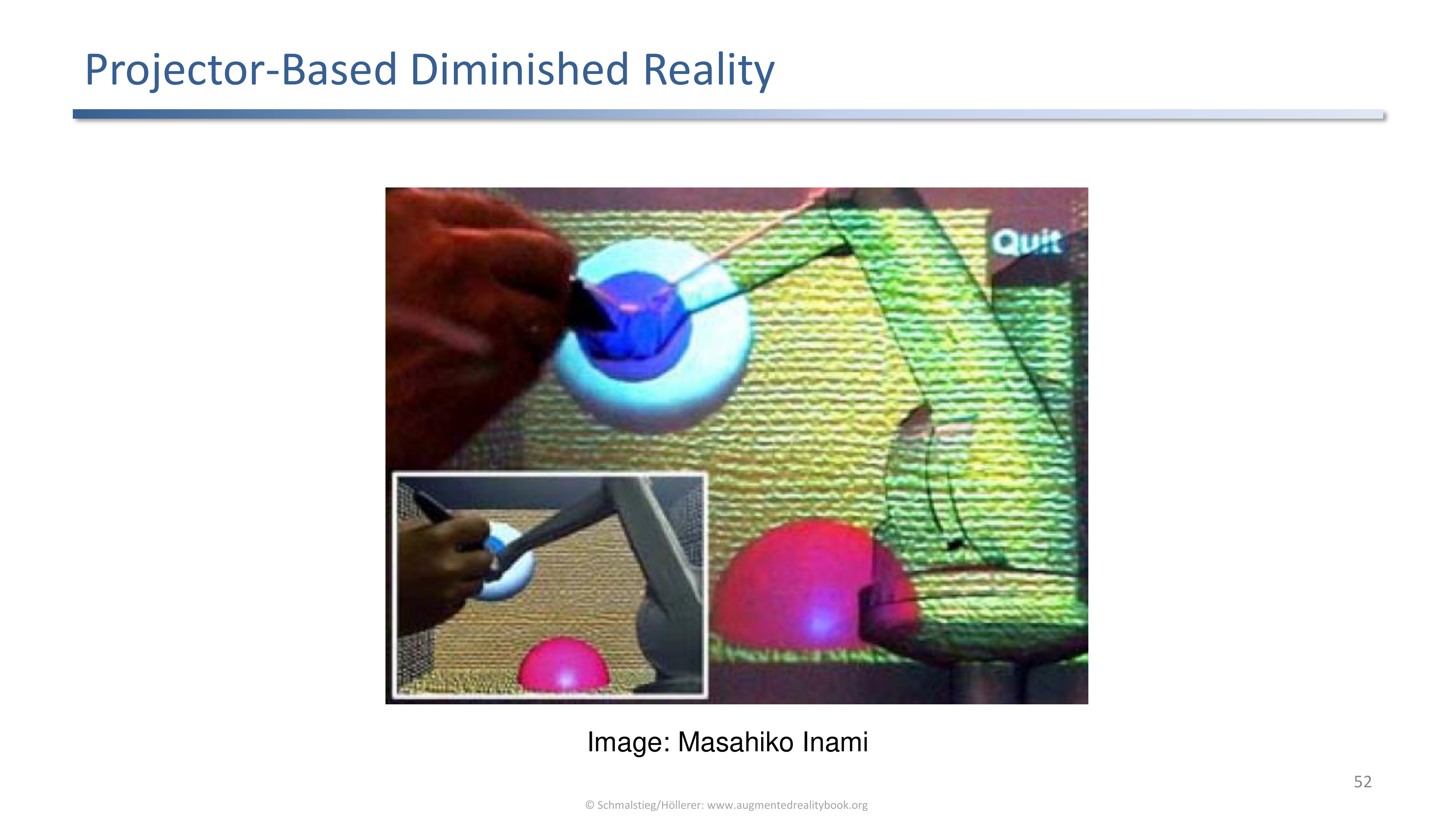
A projector erases objects by projecting the background back over them in physical space (Inami) rather than only in the rendered frame.
Works in optical see-through scenarios where the user looks at the real world directly: the projector reaches the object the same way a paintbrush would.
Stylized Augmented Reality
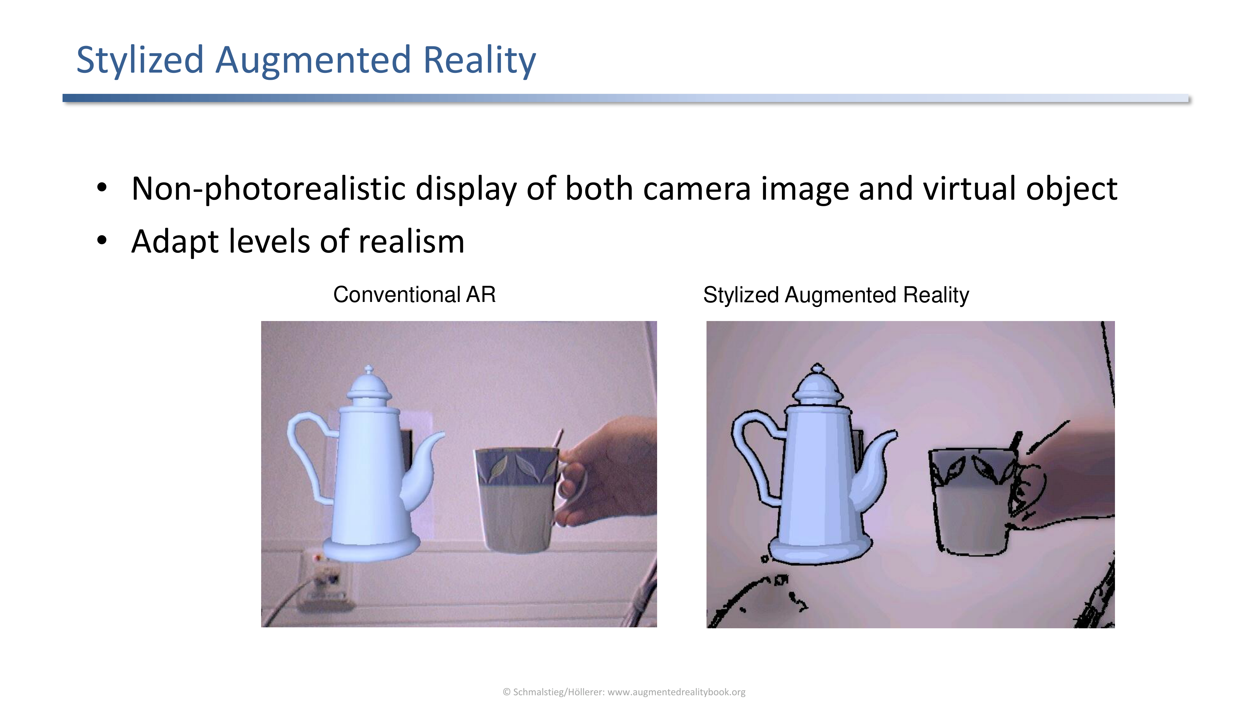
Stylized AR uses non-photorealistic rendering for both camera image and virtual content so the levels of realism agree.
The asymmetry between a photo-realistic background and a cartoonish virtual object is itself a cue that the virtual one is fake. Stylizing both halves removes that asymmetry.
Stylized AR Pipeline
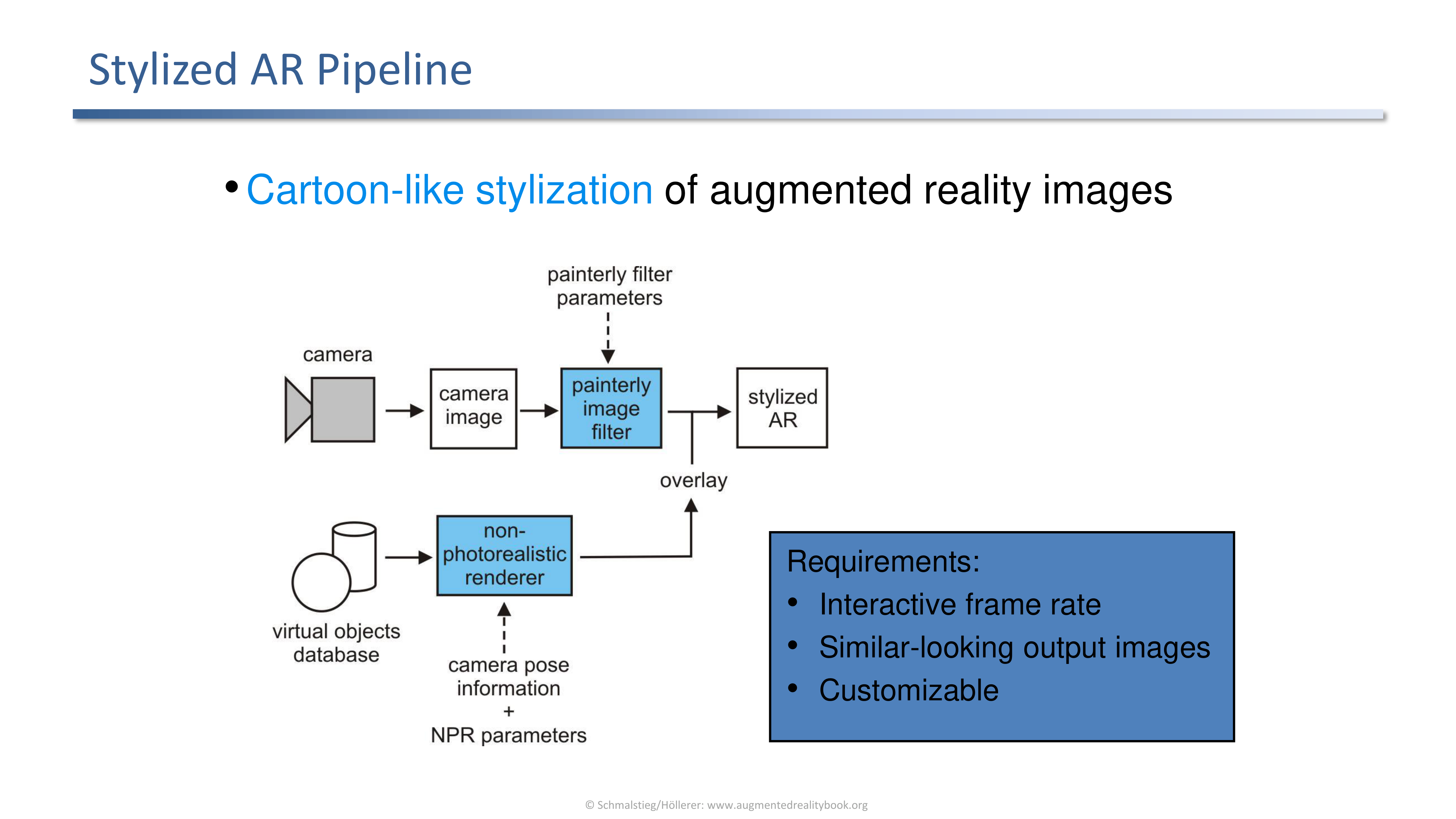
A cartoon stylization pipeline for AR must run at interactive frame rate, give similar output for the real and virtual halves, and be customizable.
Three requirements that constrain how the stylization can be implemented: speed, consistency, and tunability.
Cartoon Rendering in Augmented Reality
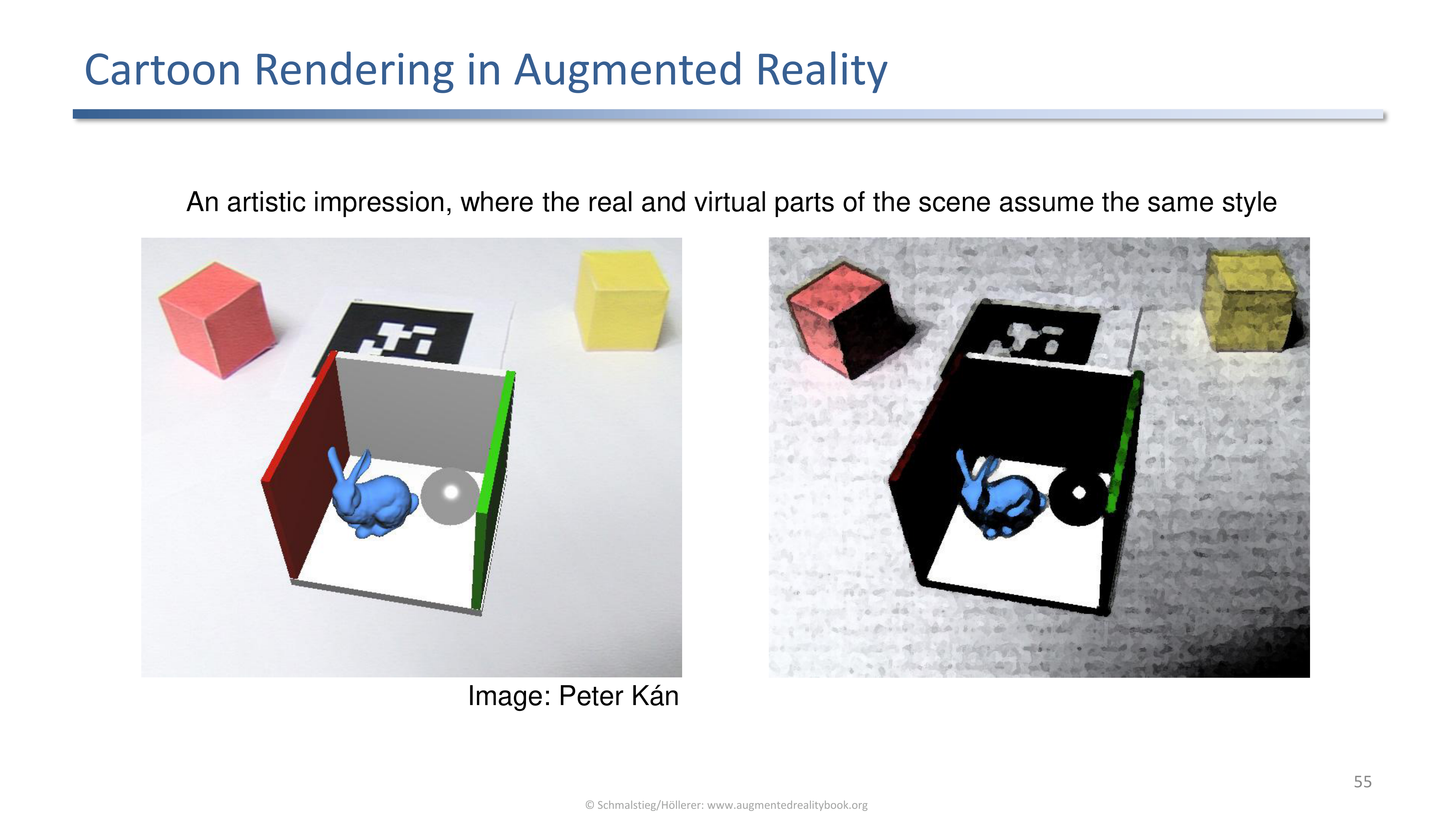
An artistic example where the real and virtual parts of the scene assume the same cartoon style.
When the style is strong enough, the eye stops asking which pixels are real.
Loose and Sketchy Augmented Reality
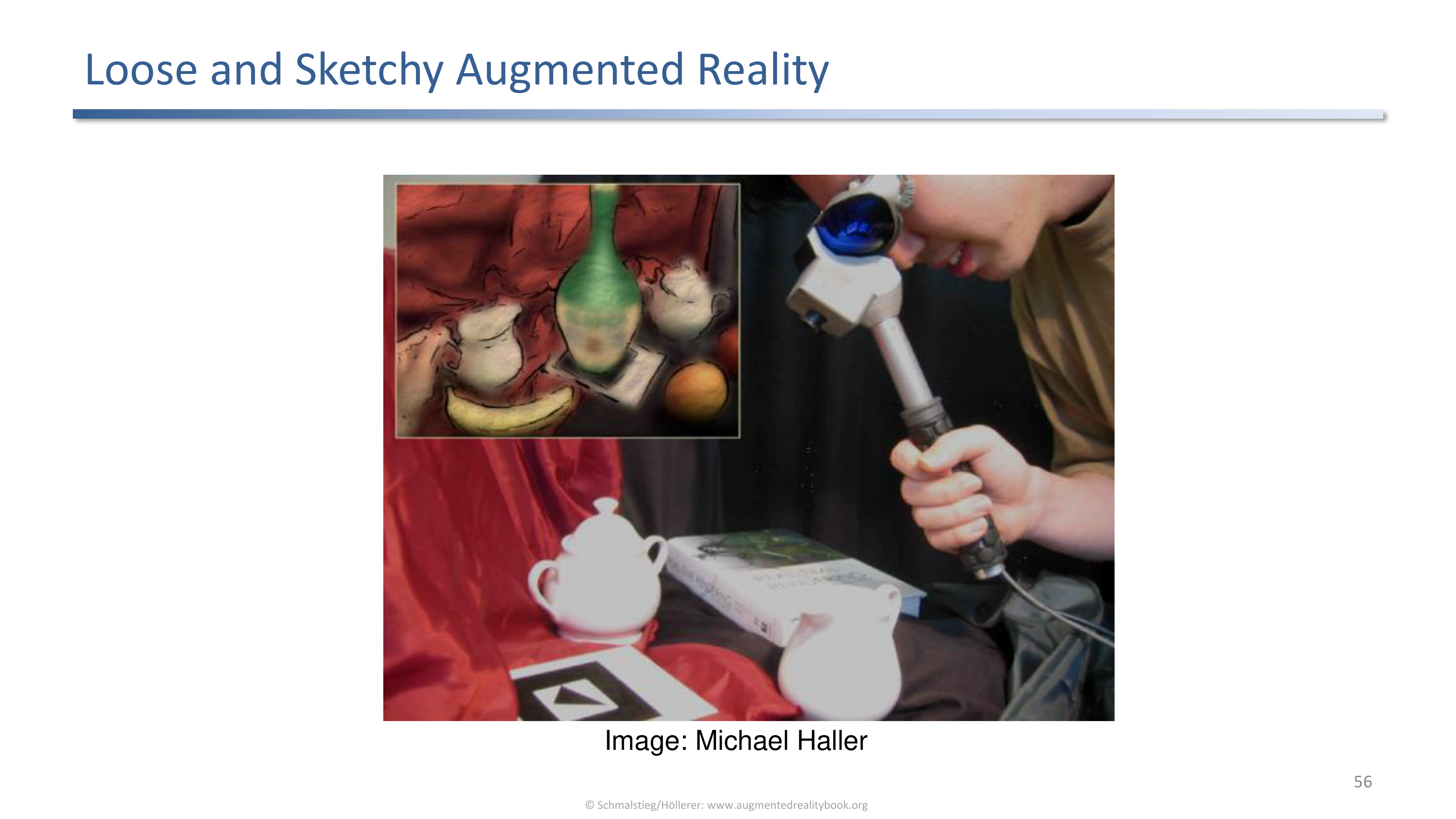
A sketchy, hand-drawn style is another way to put both halves on the same artistic register. The varying strokes hide registration jitter as part of the style.
A bonus side-effect: small registration errors look intentional under a sketchy stroke style.
7. Camera Effects
Lens Distortion
Wide-angle lenses are good for tracking but are not pinhole. Two approaches: texture-based (Watson and Hodges 1995, render undistorted then warp) or geometry-based (move vertices in projection).
The geometry of the virtual content has to match the lens of the captured video, otherwise straight virtual lines and curved real lines disagree.
Image-Space Undistortion
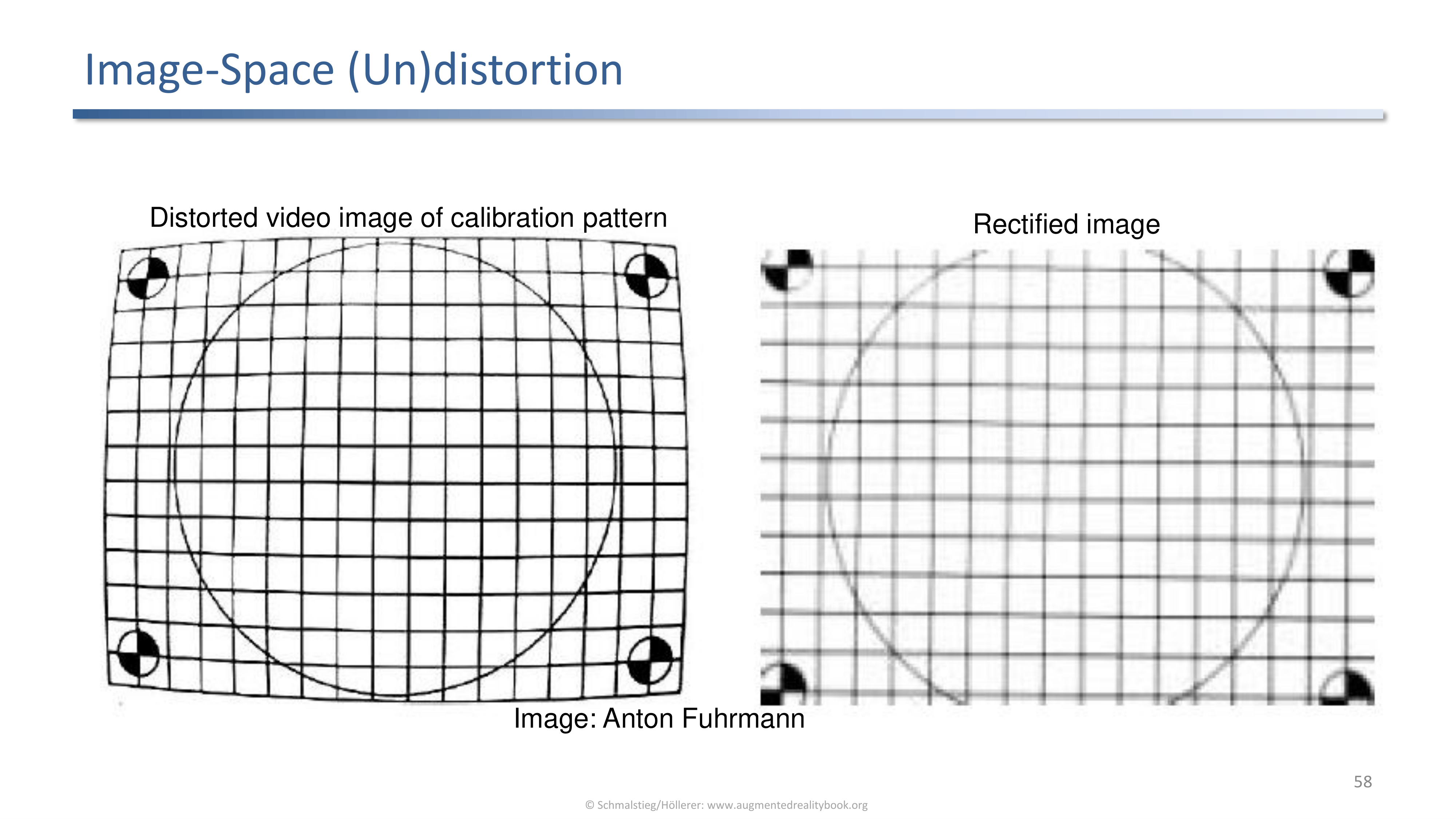
A distorted calibration pattern and the same frame rectified by an image-space undistortion warp.
The same warp also turns the rendered output into a distorted image that matches the video. The trade-off is an extra texture pass per frame.
Geometry-Based Undistortion
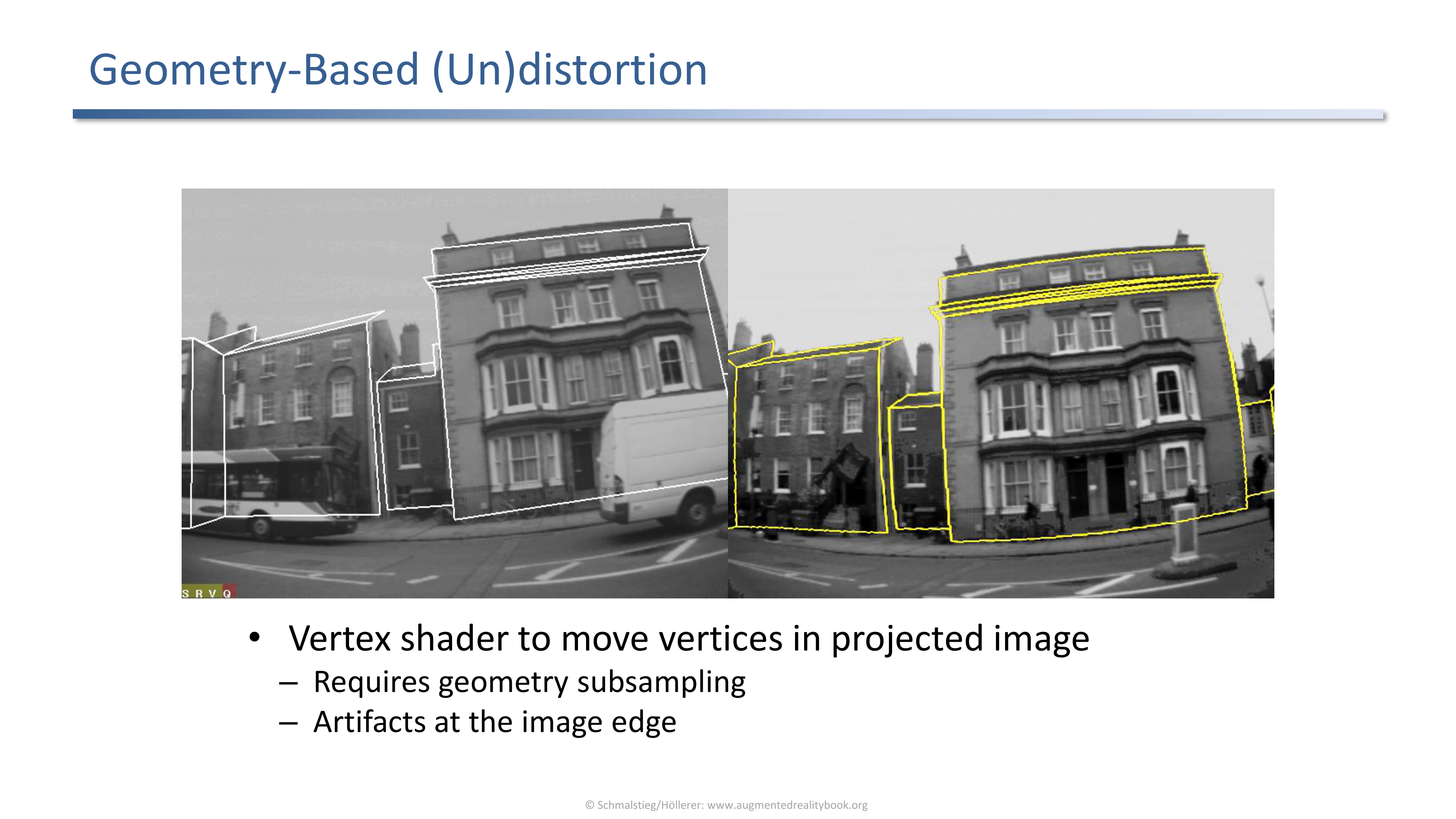
A vertex shader moves projected vertices to match the lens distortion. Requires geometry subsampling and produces artifacts at the image edge.
Avoids the extra texture pass but inherits geometric artifacts. Practical when geometry density is already high.
More Camera Effects
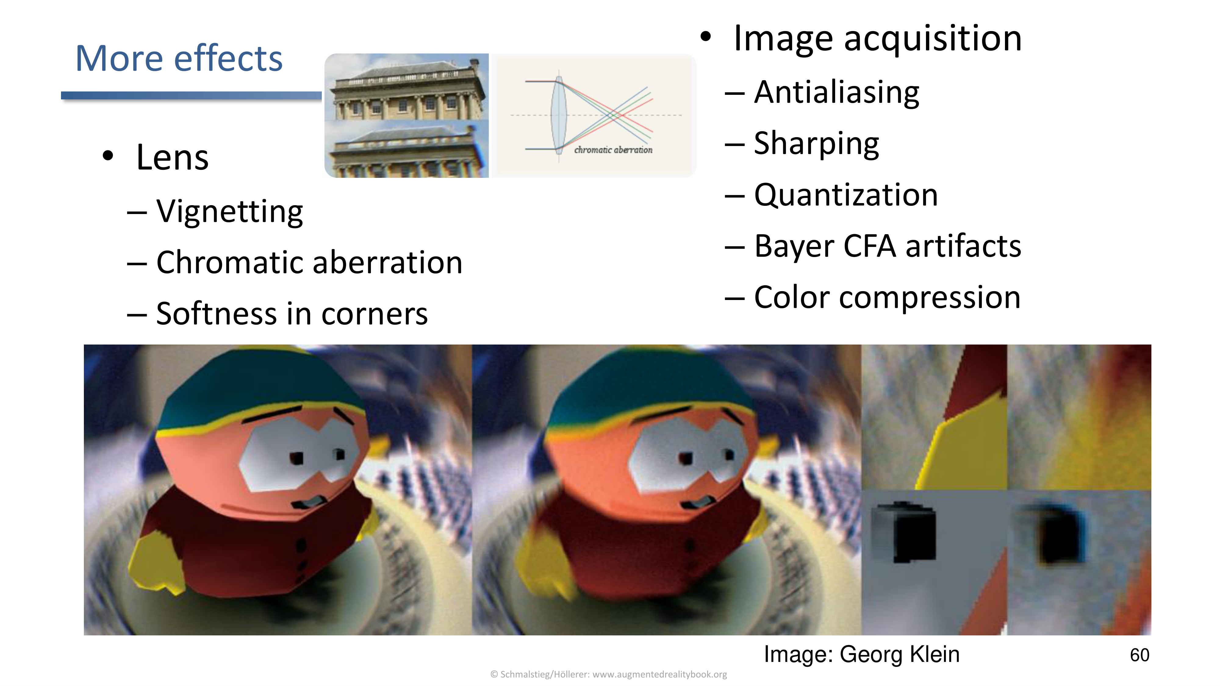
Real cameras add vignetting, chromatic aberration, corner softness, plus image acquisition effects such as antialiasing and sharpening.
For visual coherence the rendered virtual content should reproduce these. The cheap ones (vignetting, chromatic aberration, simple noise) are easy in post-processing; the expensive ones (depth defocus, motion blur) require modifying the 3D rendering.
Emulating Camera Effects in Post-Processing
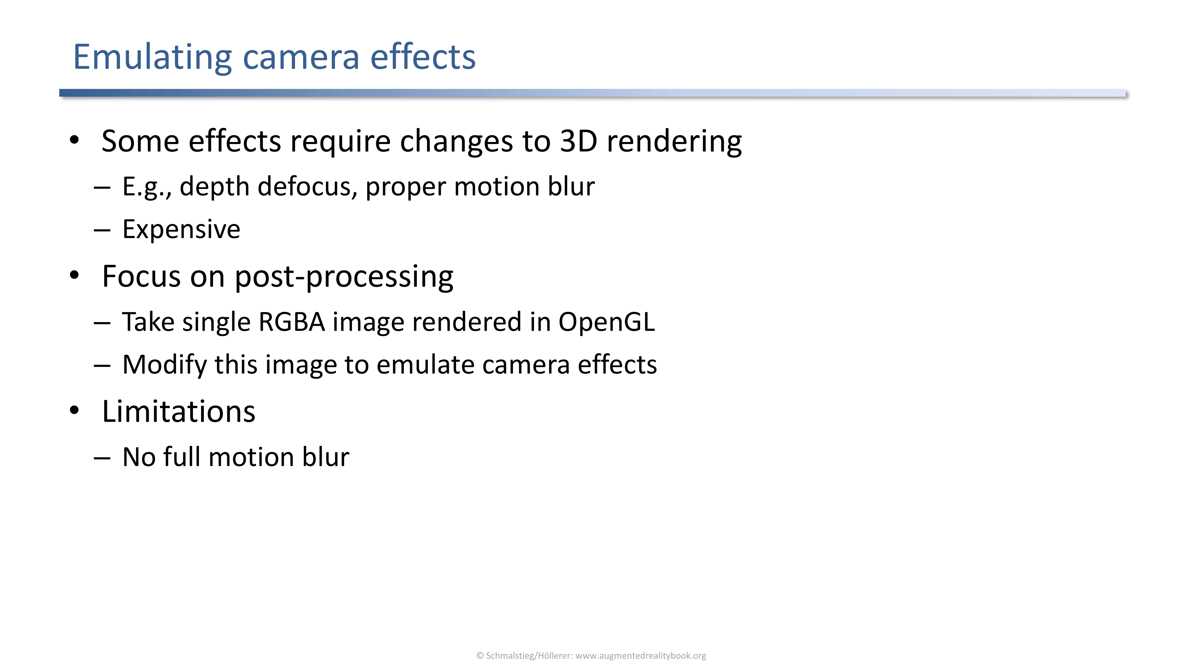
Practical compromise: take a single RGBA frame rendered in OpenGL and modify it in post-processing. Limitations: no proper motion blur.
Post-processing trades fidelity for cost. For interactive AR the cost wins and the missing depth defocus or motion blur is a known approximation.
Applied Exam Focus
- VR has full geometry, AR only has compositing of video and rendered content. Every coherence cue has to be reconstructed.
- Occlusion: phantom rendering with depth buffer (1. video, 2. disable color, 3. phantoms, 4. enable color, 5. virtual); edge occlusion refinement; probabilistic blending; depth-from-CV or a depth sensor; virtual studio segmentation; hand segmentation by skin color.
- Illumination: local versus distant split, environment cube map, light probes (chrome sphere, diffuse sphere, omnidirectional camera, textured target), photometric registration, learned light probes, light-source estimation from shadows.
- Shadows: four relations (real-real, real-virtual, virtual-real, virtual-virtual); drop shadow on plane; shadow volumes; AR multi-pass shadow volumes; differential rendering subtracts the same-without-virtual rendering; differential path tracing and photon mapping for global illumination; watch out for double shadowing.
- Reflections and refractions: real-time ray tracing of real mirrors and virtual transparent objects.
- Visual special effects: diminished reality (marker removal by texture synthesis, haptic device removal, PixMix, projector-based); stylized AR (cartoon, loose and sketchy) puts both halves on the same artistic register.
- Camera effects: lens distortion (texture-based versus geometry-based undistortion); vignetting, chromatic aberration, corner softness; depth defocus and motion blur are expensive, the rest can be done in post-processing.
Self-Check
- Why does AR need a strategy for occlusion while VR does not?
Answer
VR has a full computer graphics model of the scene, so the depth buffer resolves which surface is in front for every pixel and occlusion is automatic. AR only has the video stream plus rendered virtual content; there is no native depth for the real objects in the frame. Without an extra representation (a phantom mesh, a depth map, a segmentation mask) the renderer cannot know whether a real object should hide a virtual one.
- Write out the phantom rendering pipeline step by step and explain what each step is for.
Answer
- Draw the video so the colour buffer holds the real scene. 2. Disable writes to the colour buffer (
glColorMaskorglBlendFunc(0,1)) so subsequent draws only touch depth. 3. Render the phantoms of the real objects; they populate the depth buffer at the right registered positions. 4. Enable colour writes again. 5. Render the virtual objects normally; the depth test now compares them against the phantoms and hides parts that are behind real geometry. The depth buffer is the channel through which the real geometry communicates with the virtual rendering.
- When does edge occlusion improve on phantom rendering, and why?
Answer
When the phantom model is slightly inaccurate or misregistered, the occlusion boundary computed from the phantom does not coincide with the real silhouette in the video, which the eye notices. Edge occlusion detects the true real edge in the video near the projected phantom edge and alpha-blends the corrected boundary back. The phantom still provides depth ordering, but the silhouette is pulled to where the image actually has a contour.
- What is the difference between a light probe and an environment map, and how are they used together?
Answer
A light probe is the physical instrument that captures incident light from the scene (a chrome or diffuse sphere, or an omnidirectional camera). An environment map is the data structure (typically an HDR cube map with six faces) that stores that incident light for the renderer to sample. The probe is the measurement, the environment map is the representation. The renderer samples the environment map for reflections, diffuse irradiance, and image-based shading of the virtual objects.
- Sketch how differential rendering produces a shadow without baking it onto the video.
Answer
Render the scene with the virtual object in place using a phantom of the real geometry: that gives
L_with. Render the same scene without the virtual object: that givesL_without. ComputeL_with − L_without; this difference is the contribution of the virtual object, including any new shadows it casts on the phantom and any indirect bounces. Add that difference to the live videoLC. The video itself never gets a manual shadow drawn on it; the shadow appears because the difference is negative in the shadowed region.
- Why is double shadowing a problem, and what avoids it?
Answer
A region of the video that already lies in shadow from a real object should not become darker just because a virtual object would also cast a shadow there. Naively adding the virtual shadow yields a doubly-darkened region. Differential rendering avoids the issue because the subtraction
L_with − L_withoutonly adds the incremental shadow that was not already present, and the shadow over an already-shadowed region cancels out. Explicit reasoning about real shadows is the other escape hatch.
- Stylized AR sidesteps the realism problem. How does it gain visual coherence?
Answer
The eye reads inconsistency in style as evidence that the virtual content is fake. If both halves of the image (the camera frame and the rendered virtual content) are converted into the same non-photorealistic register (cartoon outlines, sketchy strokes, flat shading), they look like they belong to a single artistic world. The user stops comparing them to physical reality because neither half claims to be photographic.
- Why does the rendered virtual content need to match the camera’s lens distortion, and what are the two common ways to do it?
Answer
The video frame is taken through a real lens that bends straight lines. If the virtual content is rendered through an undistorted pinhole projection and composited on top, virtual straight lines stay straight while the real ones curve, and the seam between the two becomes visible especially at the image edges. The image-space approach renders undistorted, then warps the result through a texture pass that applies the lens distortion (extra pass per frame). The geometry-based approach moves the projected vertices in a vertex shader (no extra texture pass, but requires geometry subsampling and produces artifacts at the edges).
Previous: (y-07) Calibration and Registration | AR Index | Next: (y-09) Perception and Psychology