Back: (y-10) Real-Time Global Illumination | RTG Index | Next: (y-12) High Dynamic Range
Mental Model First: A Second Pipeline Next to the Rasterizer
- Raytracing is now a first-class GPU pipeline, not a software hack. Modern GPUs ship dedicated RT cores that do one thing in hardware: intersect a ray with a box, sphere, or triangle. Everything else (which rays to shoot, what to do on a hit) is programmable, exactly like the rasterization pipeline is programmable around its fixed-function rasterizer.
- The shape of the raytracing pipeline mirrors rasterization but inverts the input. Rasterization takes a triangle and produces pixels; raytracing takes a pixel, generates a ray, and asks the scene what that ray hits. Both end in a shaded image, but the raytracing pipeline replaces the vertex/rasterizer/fragment stages with ray-generation, intersection, and hit/miss shaders.
- Five new shader types replace the two old ones. Ray-generation (spawn rays), intersection (custom primitive tests), closest-hit (shade the nearest hit), any-hit (per-hit callback, e.g. for transparency), and miss (nothing was hit). The hardware drives a traversal loop that calls these callbacks at the right moments.
- A full-frame raytrace is still too expensive, so production is hybrid. At full HD you can afford only about 1-5 rays per pixel. So the main image is rasterized and raytracing is sprinkled on top for the effects rasterization does badly: shadows, ambient occlusion, reflections, and indirect light. Same materials, same data, two pipelines cooperating.
- Because rays are scarce, every raytraced effect is noisy, and denoising is mandatory. One ray per pixel is high-variance. The real engineering is in the reconstruction stack: spatial bilateral filters, temporal reprojection, and neural denoisers (DLSS Ray Reconstruction) that turn a handful of noisy rays into a clean image.
1. Raytracing Cores: New Fixed-Function Hardware
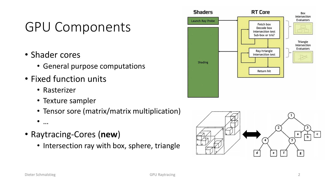
L11_Pg-02: GPU components - programmable shader cores plus fixed-function units (rasterizer, texture sampler, tensor cores), now joined by raytracing cores that intersect a ray with a box, sphere, or triangle.
A modern GPU is a mix of programmable shader cores and fixed-function units. The fixed-function list used to be the rasterizer and the texture sampler; recently it gained tensor cores (matrix-matrix multiply, used by ML and denoisers) and raytracing cores. The RT core does exactly one job in silicon: test a ray against a bounding box, sphere, or triangle. That one acceleration is what makes raytracing fast enough to mix into a real-time frame.
2. Rasterization vs. Raytracing Pipeline
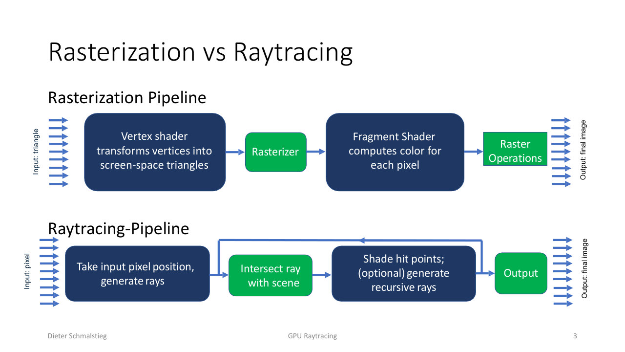
L11_Pg-03: The two pipelines side by side. Rasterization: vertex shader transforms triangles, rasterizer makes fragments, fragment shader colours each pixel. Raytracing: generate rays from pixel positions, intersect with the scene, shade hit points and optionally spawn recursive rays.
The raytracing pipeline is the structural mirror image of rasterization:
- Rasterization takes a triangle as input. The vertex shader transforms vertices into screen-space triangles, the fixed-function rasterizer turns triangles into fragments, the fragment shader computes a colour per pixel, and raster operations write the final image.
- Raytracing takes a pixel as input. It generates rays from pixel positions, intersects each ray with the whole scene, shades the hit point, and (optionally) spawns recursive rays for reflections or shadows before writing the final image.
The key inversion: rasterization streams geometry and only ever sees one triangle at a time, while raytracing queries the entire scene per ray. That global view is exactly why raytracing handles reflections and shadows naturally and why it needs an acceleration structure to be tractable.
3. The Five Raytracing Shader Types
The fixed-function RT core handles intersection, but the behaviour around it is programmable through five shader types. Two define what rays exist, three define what happens to a ray.
- Ray-generation shader: starts the whole process, usually invoked once per pixel at the beginning. It calls
TraceRay(). - Intersection shader: tests a ray against a primitive. Reusable; only needed for non-triangle primitives, since triangle intersection is hardware-accelerated.
- Closest-hit shader: callback for the first (nearest) intersection. This is where surface shading happens.
- Any-hit shader: callback for every candidate intersection along the ray, e.g. to handle transparency by accepting or ignoring a hit.
- Miss shader: callback when the ray hits nothing (background, sky, or “light is visible” for a shadow ray).
Ray Generation Drives Everything
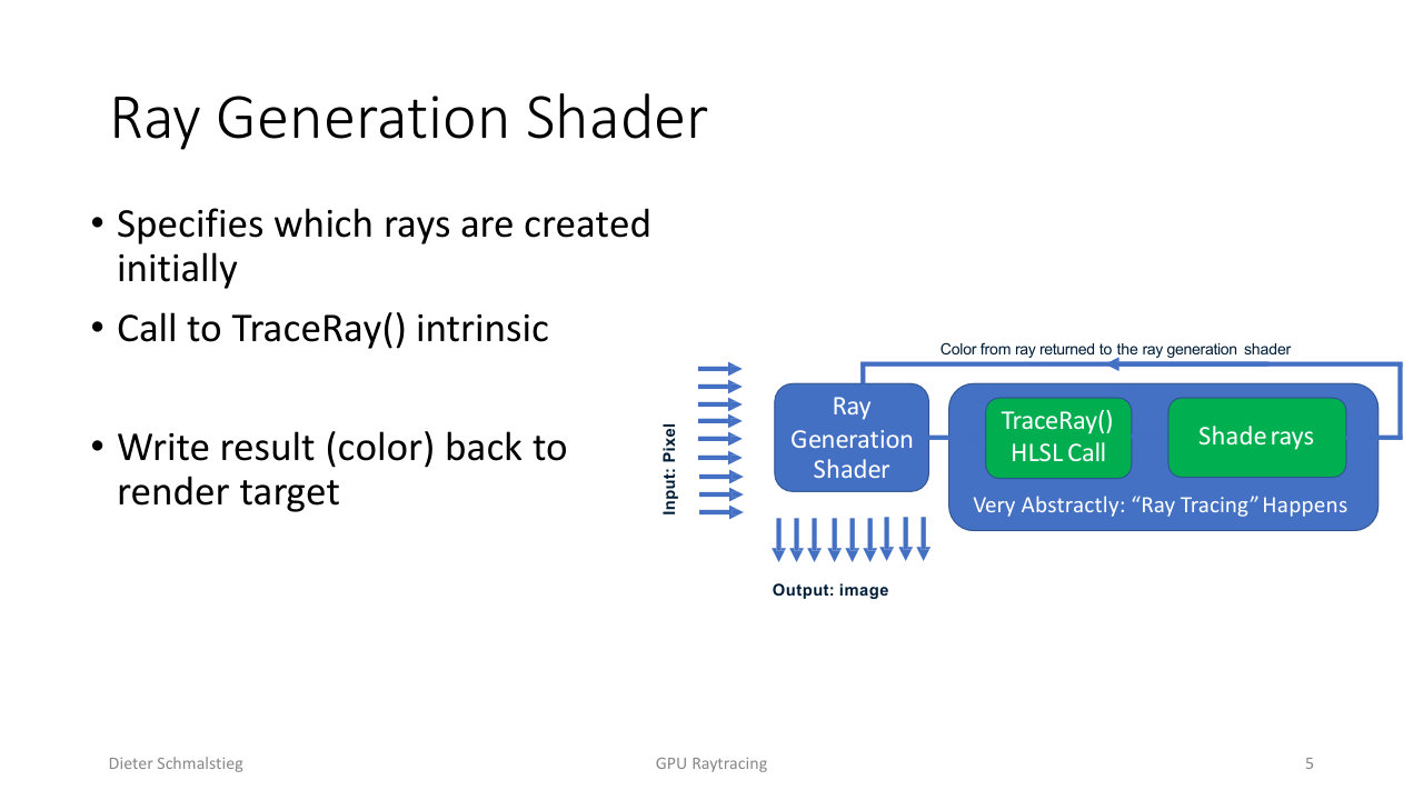
L11_Pg-05: The ray-generation shader takes a pixel, calls the TraceRay() HLSL intrinsic, "ray tracing happens", and the resulting colour is returned to the ray-generation shader to write into the render target.
The ray-generation shader is the entry point. It computes a ray for the current pixel, calls TraceRay(), and abstractly “ray tracing happens” inside that call. Whatever colour the trace resolves to comes back to the ray-generation shader, which writes it to the output image.
The Hit/Miss Decision
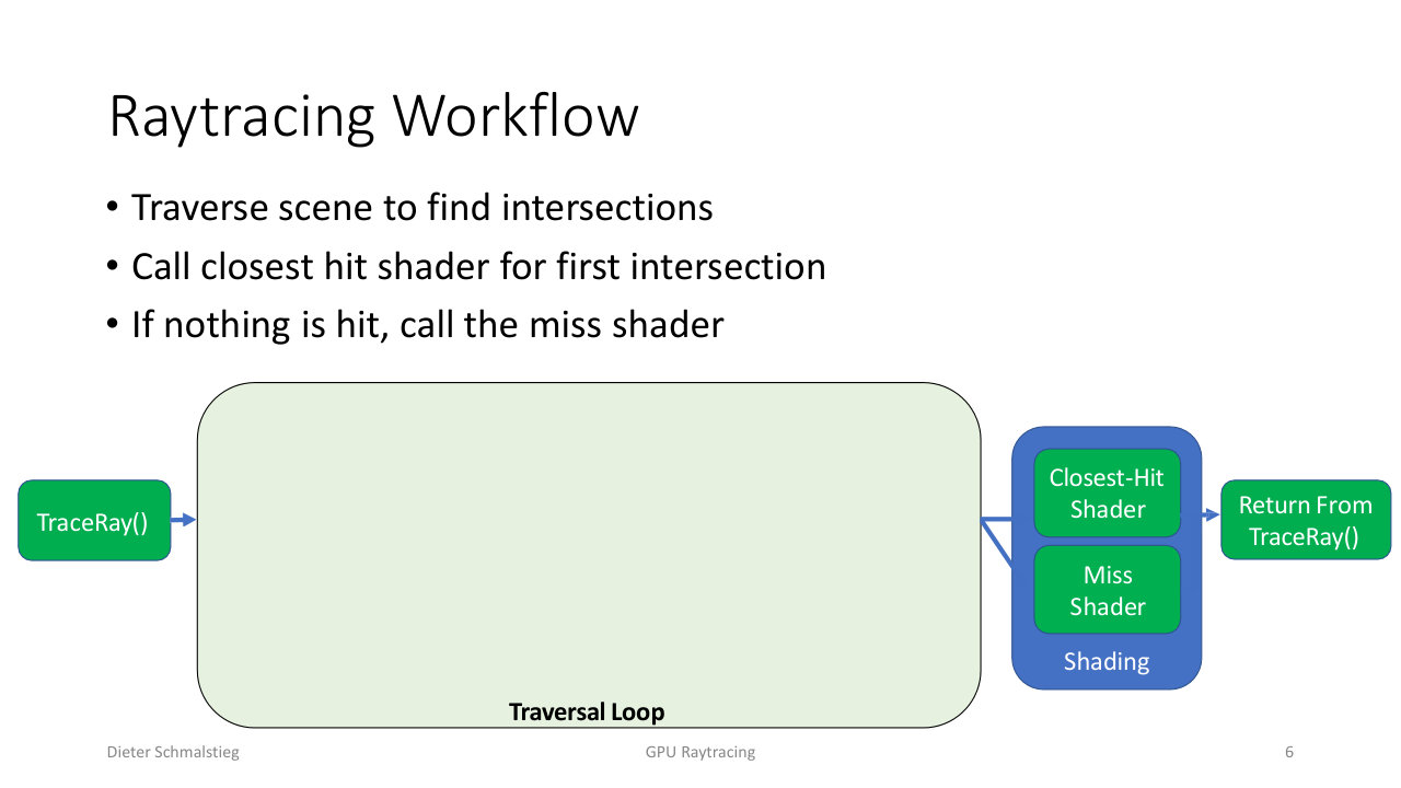
L11_Pg-06: Inside TraceRay(), the traversal loop walks the scene. On the first intersection it calls the closest-hit shader; if nothing is hit it calls the miss shader; either way control returns from TraceRay().
Inside TraceRay() the hardware traverses the acceleration structure looking for intersections. When it finds the closest one it invokes the closest-hit shader for shading; if the ray escapes the scene it invokes the miss shader. Both paths return control (and a payload) back to the caller.
4. The Traversal Loop
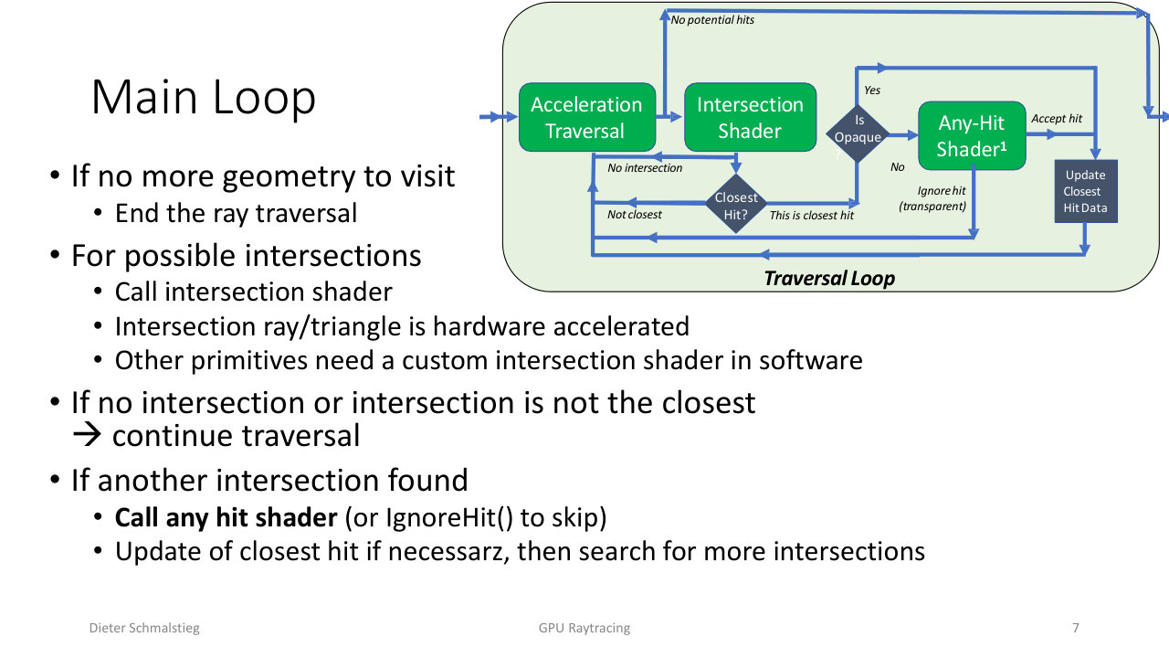
L11_Pg-07: The main traversal loop. Acceleration-structure traversal yields candidate hits; the intersection shader confirms them; any-hit can ignore a hit (transparency) or accept it; the closest hit is tracked until traversal ends, then the closest-hit shader runs.
The hardware-driven main loop is the heart of the pipeline:
- Acceleration traversal walks the bounding-volume hierarchy. If there are no more potential hits, traversal ends.
- For each candidate, the intersection shader runs. Triangle intersection is hardware-accelerated; other primitives need a custom software intersection shader.
- If there is no intersection, or it is not the closest so far, traversal continues.
- If a valid intersection is found, the any-hit shader runs. It can
IgnoreHit()(e.g. a transparent surface) or accept the hit. - On an accepted opaque hit, the closest-hit data is updated, and the loop keeps searching for anything closer.
- When traversal finishes, the closest-hit shader shades the nearest accepted intersection.
The any-hit / opaque branch is what lets alpha-tested foliage and transparency work: the any-hit shader decides per candidate whether the hit counts.
5. Ray Payload and Intersection Attributes
Payload: Per-Ray State
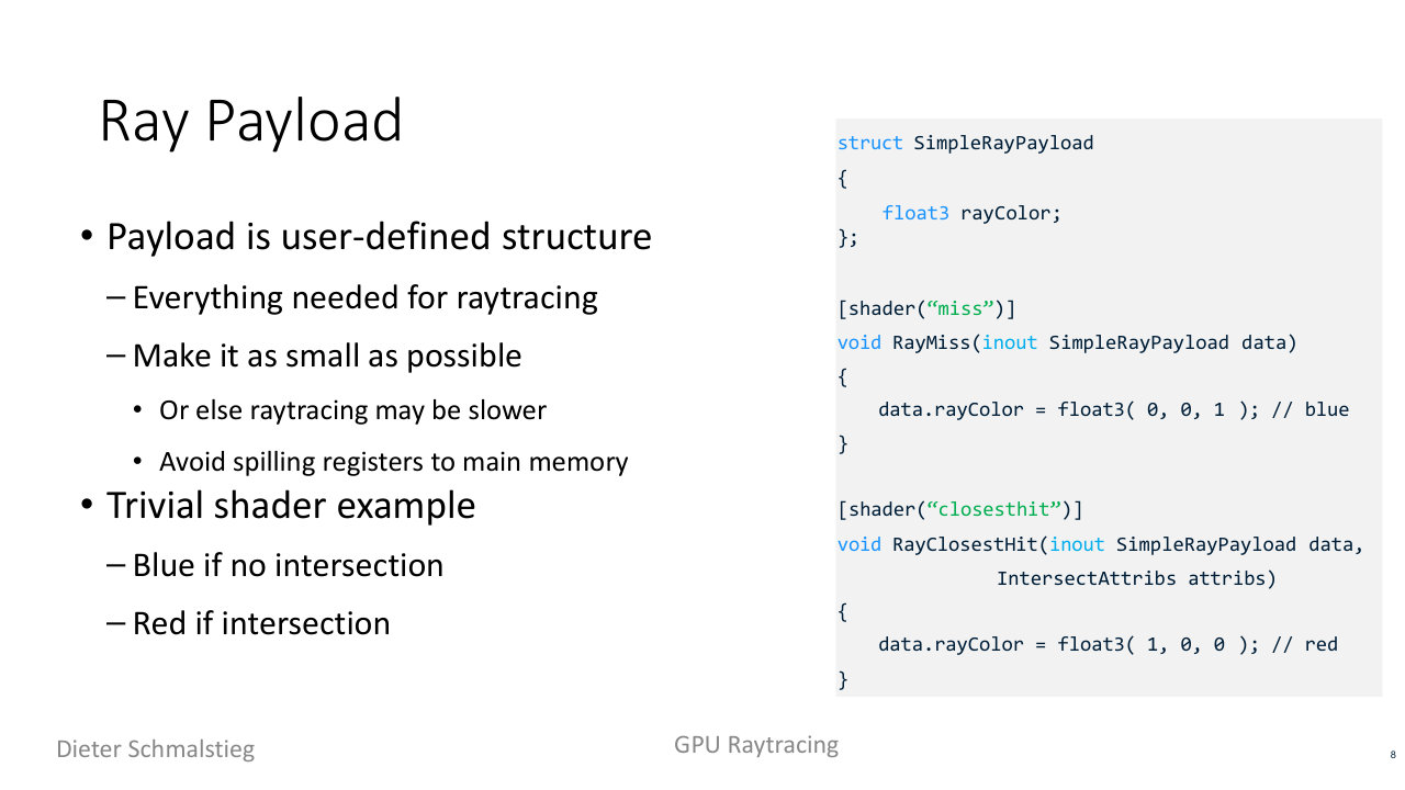
L11_Pg-08: A minimal ray payload - a user struct carrying a colour. The miss shader writes blue, the closest-hit shader writes red. Keep the payload as small as possible to avoid spilling registers to memory.
The payload is a user-defined struct that travels with the ray and carries everything the shaders need to communicate (accumulated colour, recursion depth, random seed). It must be kept as small as possible: a fat payload spills registers to main memory and slows tracing down. The trivial example shows the pattern - a payload holding float3 rayColor, with the miss shader writing blue and the closest-hit shader writing red:
struct SimpleRayPayload { float3 rayColor; };

[shader("miss")]
void RayMiss(inout SimpleRayPayload data) {
    data.rayColor = float3(0, 0, 1); // blue
}

[shader("closesthit")]
void RayClosestHit(inout SimpleRayPayload data, IntersectAttribs attribs) {
    data.rayColor = float3(1, 0, 0); // red
}
Attributes: Per-Intersection Data
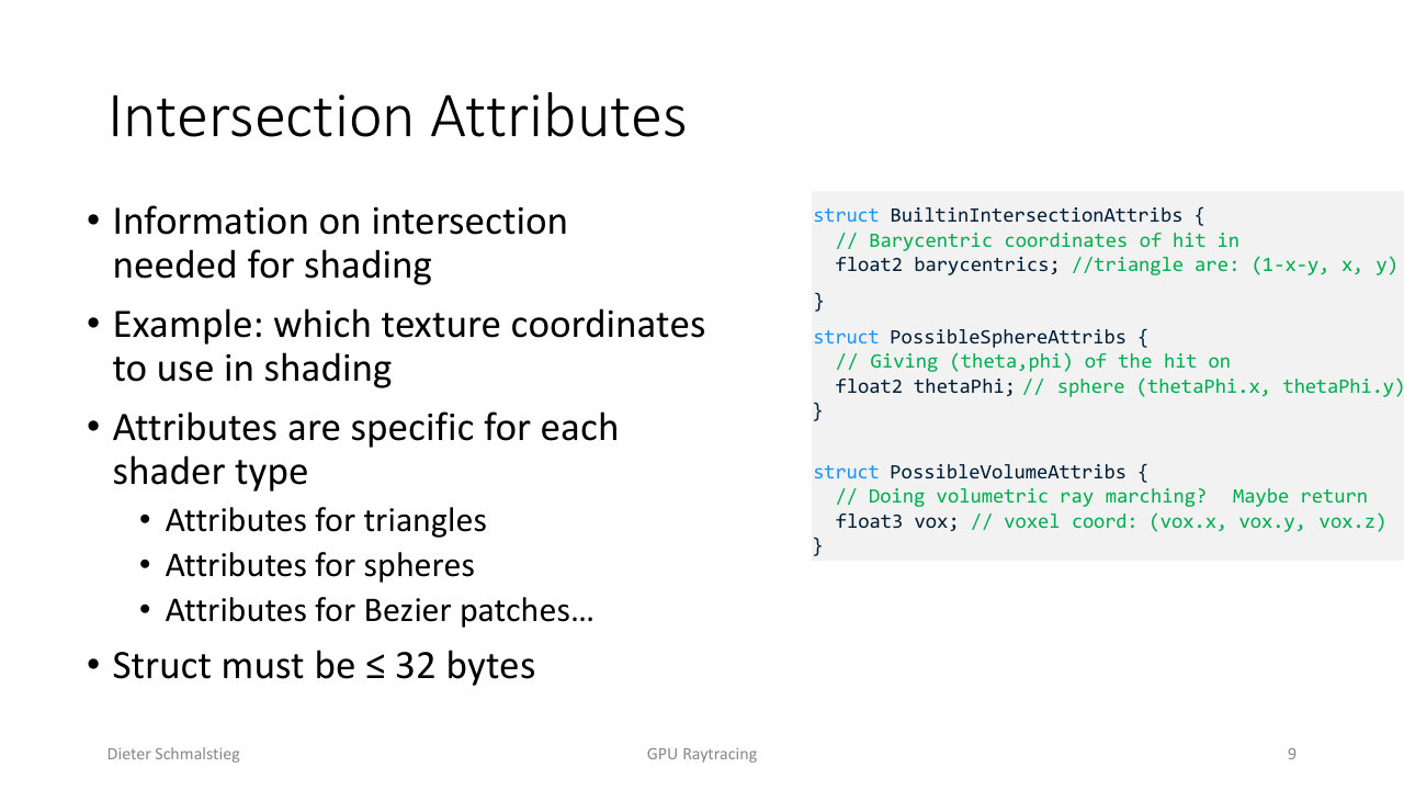
L11_Pg-09: Intersection attributes describe the hit itself - barycentric coordinates for a triangle, (theta, phi) for a sphere, voxel coordinate for a volume. The struct must be at most 32 bytes and is specific to each primitive type.
Where the payload is per-ray, intersection attributes are per-intersection: the data needed to shade the specific hit, such as which texture coordinates to use. They are primitive-specific (barycentrics for triangles, (theta, phi) for spheres, voxel coordinates for volumes) and the struct must be at most 32 bytes. The intersection shader fills the attributes; the closest-hit shader reads them to do the actual shading.
6. Host-Side Setup and Ray-Generation Code
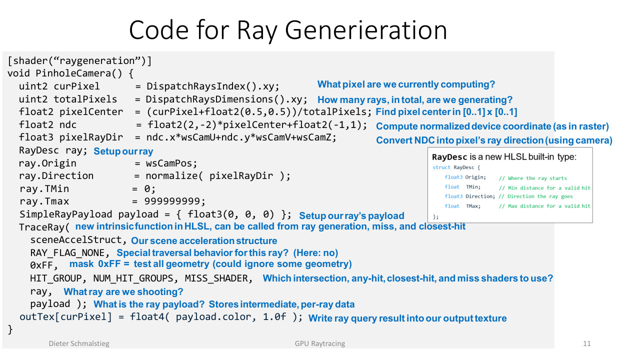
L11_Pg-11: A pinhole-camera ray-generation shader. It reads the pixel index, computes a normalized device coordinate, turns that into a world-space ray direction via the camera basis, fills a RayDesc, calls TraceRay() against the scene acceleration structure, and writes the returned colour into the output texture.
Besides the per-ray shaders, the host (C++ via the DirectX API) provides global inputs through a constant buffer: the output render target (RWTexture<float4>), the camera position and basis vectors (wsCamPos, wsCamU/V/W), and the scene’s RaytracingAccelerationStructure. The ray-generation shader then assembles a ray per pixel:
[shader("raygeneration")]
void PinholeCamera() {
    uint2 curPixel     = DispatchRaysIndex().xy;       // which pixel
    uint2 totalPixels  = DispatchRaysDimensions().xy;  // how many rays total
    float2 pixelCenter = (curPixel + 0.5) / totalPixels;       // [0..1]
    float2 ndc         = float2(2,-2)*pixelCenter + float2(-1,1); // NDC, as in raster
    float3 pixelRayDir = ndc.x*wsCamU + ndc.y*wsCamV + wsCamW;  // via camera basis

    RayDesc ray;
    ray.Origin    = wsCamPos;
    ray.Direction = normalize(pixelRayDir);
    ray.TMin      = 0;
    ray.TMax      = 999999999;

    SimpleRayPayload payload = { float3(0,0,0) };
    TraceRay(sceneAccelStruct, RAY_FLAG_NONE, 0xFF,
             HIT_GROUP, NUM_HIT_GROUPS, MISS_SHADER, ray, payload);

    outTex[curPixel] = float4(payload.rayColor, 1.0f);
}
The NDC computation is identical to the rasterization path - the camera maths is the same, only the consumer differs. The 0xFF mask means “test all geometry” (a different mask could skip some objects), and the hit-group / miss-shader indices select which shaders run for this ray. TraceRay() is a new HLSL intrinsic callable from ray-generation, miss, and closest-hit shaders, which is what makes recursive rays possible.
7. Performance and Efficiency
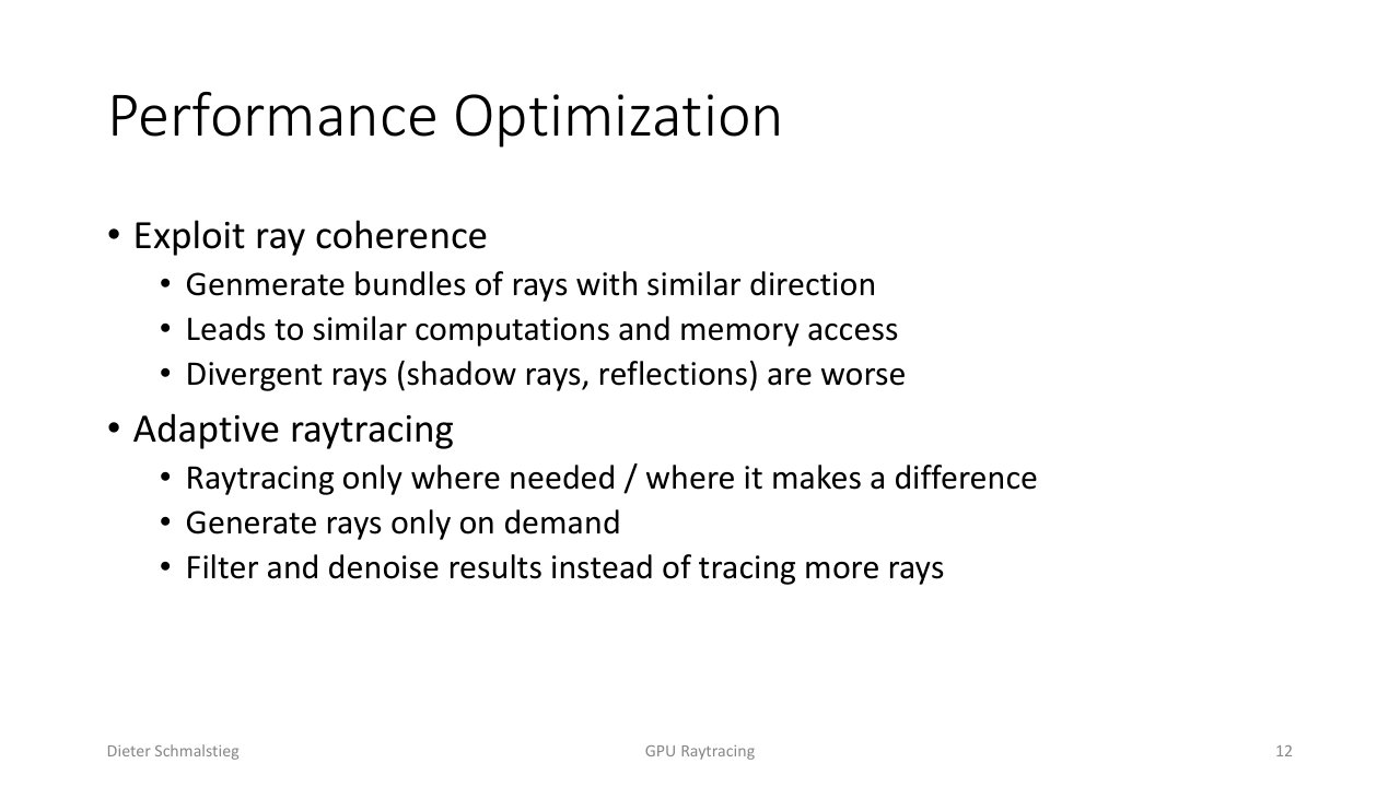
L11_Pg-12: Performance levers - exploit ray coherence by bundling rays with similar directions (similar work and memory access), and use adaptive raytracing that only shoots rays where they matter, then filter and denoise instead of tracing more.
Two big levers govern raytracing speed:
- Ray coherence: rays with similar directions touch similar memory and do similar work, so bundling coherent rays is cache-friendly. Divergent rays (shadow rays to scattered lights, glossy reflections) are the worst case because each one wanders off to different parts of the scene.
- Adaptive raytracing: trace only where it makes a visible difference, generate rays on demand, and prefer filtering/denoising over brute-force extra rays.
The cost per ray is high: roughly 1-5 rays per pixel at full HD is the budget. Consequences follow directly - often you raytrace at low resolution and upsample, every ray must count (importance sampling), and the payload must stay compact to preserve memory efficiency.
8. Hybrid Rendering: Rasterize Then Raytrace
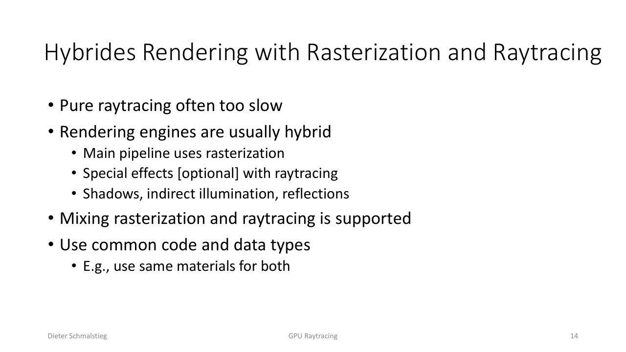
L11_Pg-14: Hybrid rendering. Pure raytracing is usually too slow, so the main pipeline rasterizes and raytracing adds optional special effects - shadows, indirect illumination, reflections - sharing common code, data types, and materials between both.
Pure raytracing is generally too slow for a whole frame, so real engines are hybrid: the main image is rasterized and raytracing is layered on for the effects rasterization struggles with - accurate shadows, indirect illumination, and reflections. The two pipelines are designed to interoperate: the same materials, shading code, and data types feed both, so a surface looks consistent whether it was rasterized or hit by a ray.
9. Raytraced Shadows
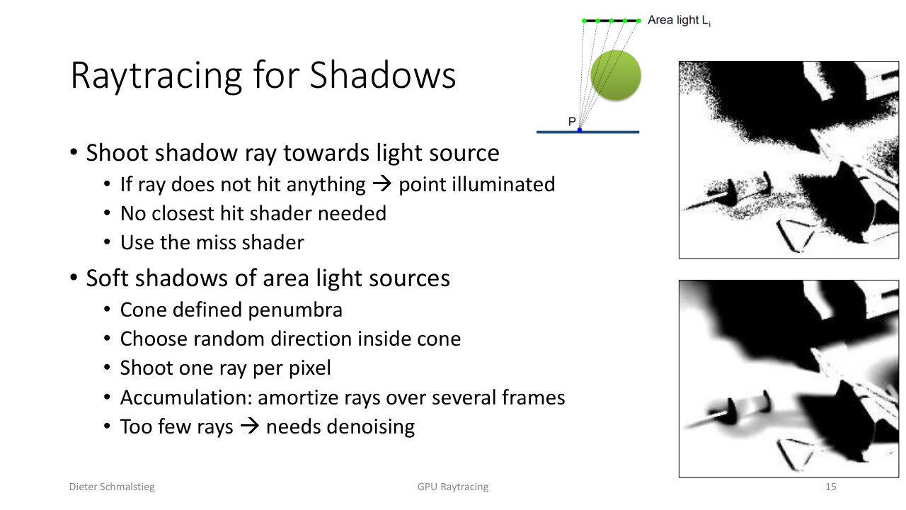
L11_Pg-15: Shadow rays. Shoot a ray toward the light; if it hits nothing the point is lit, so only a miss shader is needed. For soft shadows from an area light, pick a random direction inside the penumbra cone, shoot one ray per pixel, and amortize over frames - then denoise.
Shadows are the easiest win for raytracing. From a surface point, shoot a shadow ray toward the light. If the ray hits nothing the point is illuminated; if it hits geometry the point is in shadow. No closest-hit shader is needed - the miss shader alone signals “light is visible”, which makes shadow rays cheap.
For soft shadows from an area light, the penumbra is a cone of directions toward the light’s extent. Pick a random direction inside that cone and shoot one ray per pixel. A single random ray per frame is far too noisy, so contributions are accumulated/amortized over several frames and the result is denoised.
The Soft-Shadow Pipeline
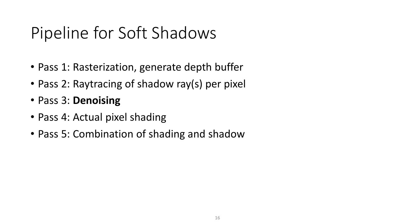
L11_Pg-16: The five-pass soft-shadow pipeline - (1) rasterize a depth buffer, (2) raytrace shadow rays per pixel, (3) denoise, (4) shade pixels, (5) combine shading with the shadow term.
The production soft-shadow pipeline interleaves both renderers across five passes:
- Rasterization generates the depth buffer (and G-buffer) of the visible surfaces.
- Raytracing shoots shadow ray(s) per pixel from those surfaces toward the light.
- Denoising cleans up the noisy one-ray-per-pixel shadow signal.
- Pixel shading computes the lit colour.
- Combination multiplies shading by the denoised shadow term.
Notice raytracing is used only for the visibility query; everything else stays in the fast rasterization path.
10. Denoising: Turning Few Rays into a Clean Image
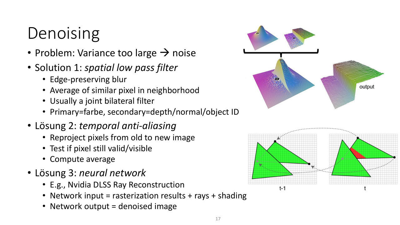
L11_Pg-17: Three denoising strategies - (1) an edge-preserving spatial low-pass (joint bilateral filter using depth/normal/object-ID as the guide), (2) temporal anti-aliasing that reprojects and validates pixels from the previous frame, and (3) a neural network such as Nvidia DLSS Ray Reconstruction.
With only a few rays per pixel the variance is large, so the raw image is noisy. Denoising is not optional polish - it is what makes raytracing viable. Three complementary strategies:
- Spatial low-pass (joint bilateral filter): an edge-preserving blur that averages only similar neighbouring pixels. The colour is the primary signal; depth, normal, and object ID are secondary guides that stop the blur from crossing edges.
- Temporal anti-aliasing: reproject pixels from the previous frame into the current one, test whether each is still valid/visible, and average. This reuses samples across time, effectively raising the ray count for free when the scene is stable.
- Neural network: e.g. Nvidia DLSS Ray Reconstruction. The network takes the rasterization results, the raw rays, and shading as input and outputs a denoised image, learning the reconstruction the hand-tuned filters approximate.
11. Ambient Occlusion and Reflections
Ambient Occlusion
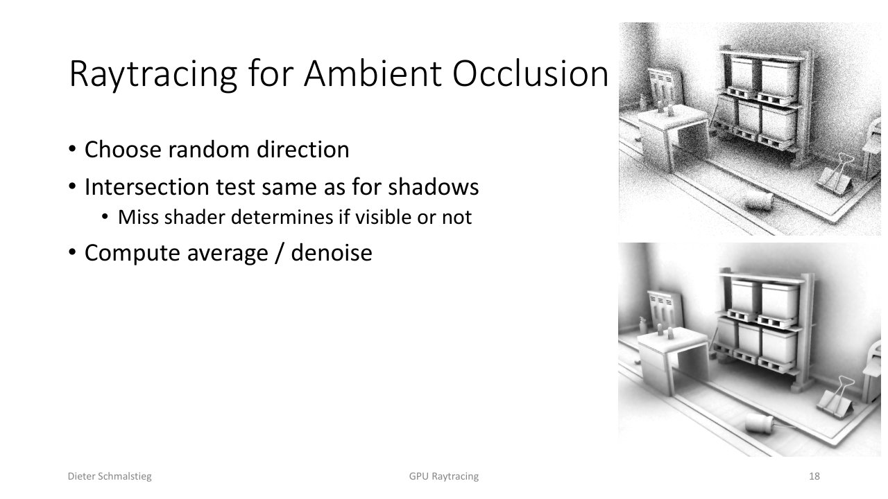
L11_Pg-18: Raytraced ambient occlusion. Shoot rays in random directions over the hemisphere; the intersection test is the same as for shadows, the miss shader decides visibility, and the average (after denoising) is the occlusion factor.
Ambient occlusion reuses the shadow machinery. From a surface point shoot rays in random hemisphere directions; the intersection test and miss-shader logic are identical to shadow rays. The fraction of rays that escape (miss) is the openness of the point; averaging and denoising gives the AO term. It is just “shadow rays toward the whole hemisphere instead of toward one light”.
Reflections
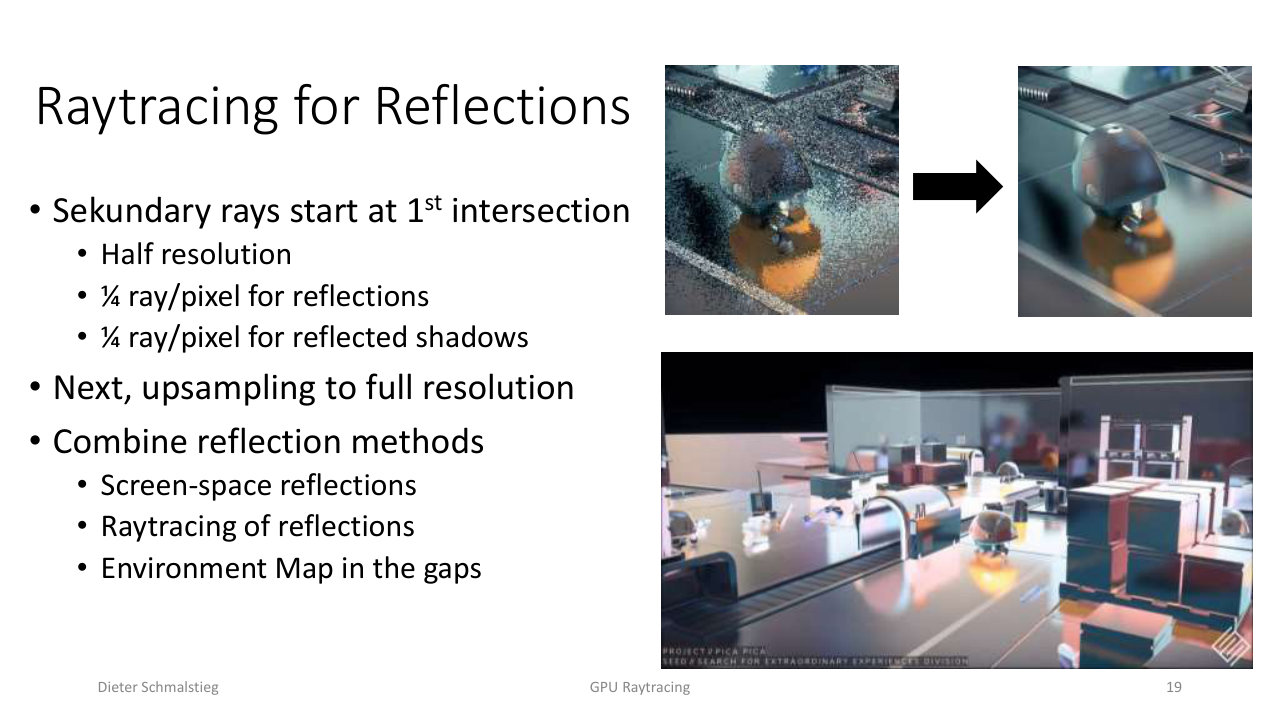
L11_Pg-19: Raytraced reflections. Secondary rays start at the first intersection, traced at half resolution (about 1/4 ray/pixel for reflections, 1/4 for reflected shadows), then upsampled. Combine with screen-space reflections and fill the gaps with an environment map.
Reflections spawn secondary rays from the primary hit point in the mirror direction. The ray budget is tight, so reflections are traced at reduced resolution - roughly a quarter ray per pixel for the reflection itself and another quarter for shadows seen in the reflection - then upsampled. In practice reflections are a blend of methods: cheap screen-space reflections where the reflected surface is on-screen, raytraced reflections where it is not, and an environment map to fill any remaining gaps.
12. The Reconstruction Stack in Pictures
The final slides walk one noisy raytraced frame through the full denoising stack, each stage adding quality on top of the last.
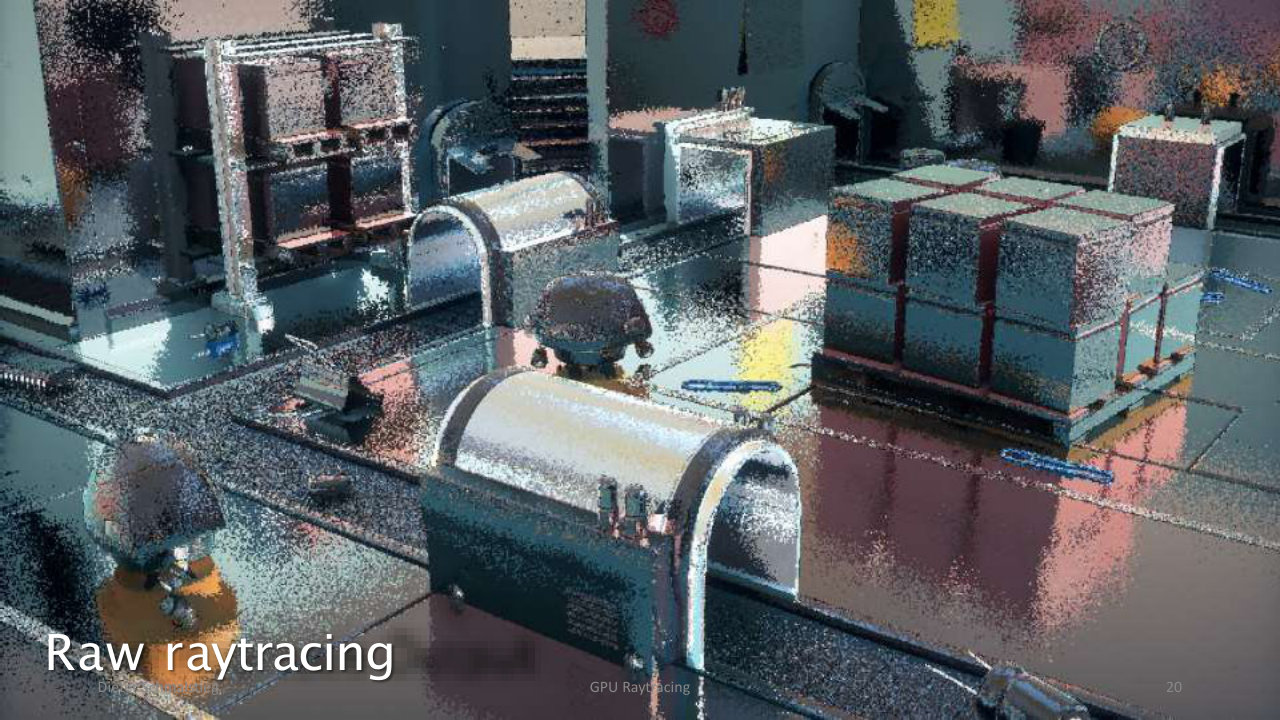
L11_Pg-20: Raw raytracing - one ray per pixel is extremely noisy, almost unreadable as an image.
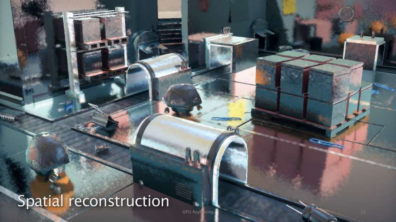
L11_Pg-21: Spatial reconstruction - an edge-aware spatial filter recovers structure from the noise.
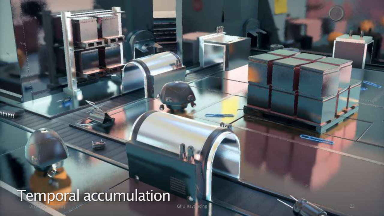
L11_Pg-22: Temporal accumulation - reusing samples from previous frames sharply reduces remaining variance.
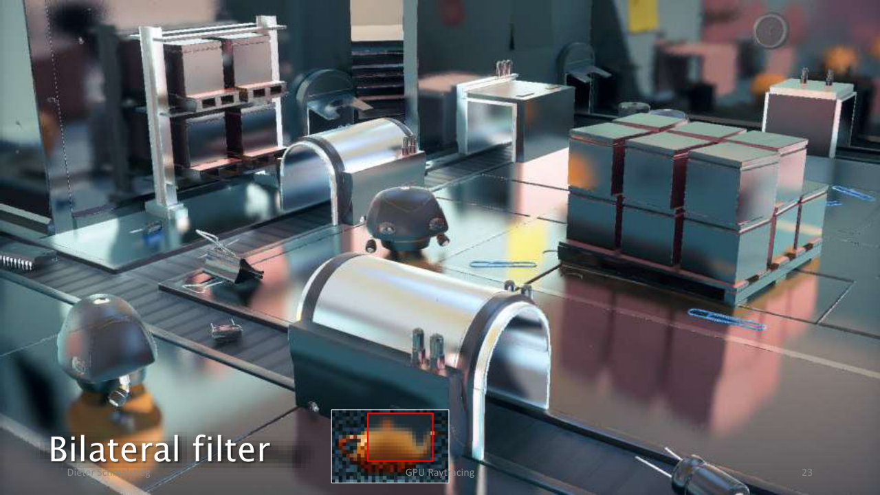
L11_Pg-23: Bilateral filter - a final joint bilateral pass cleans residual noise while preserving edges.
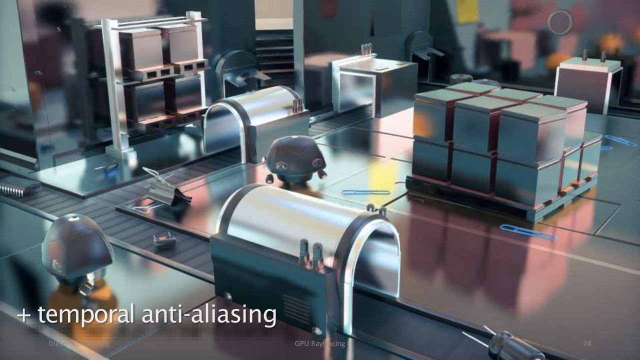
L11_Pg-24: Plus temporal anti-aliasing - edges are smoothed and the image stabilizes across frames.
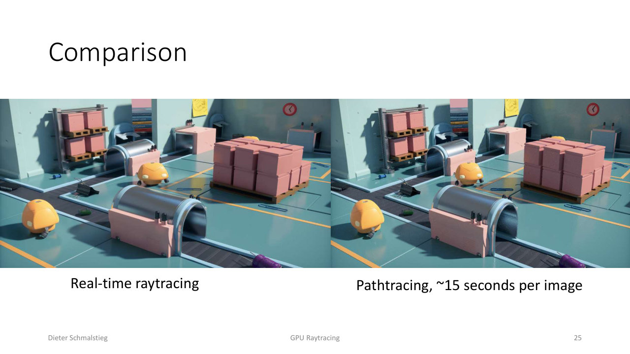
L11_Pg-25: Comparison - offline path tracing at about 15 seconds per image versus the real-time raytraced result. The reconstructed real-time image lands close to the reference at a tiny fraction of the cost.
The progression is the whole lesson in one sequence: a budget of a few rays per pixel is unusable on its own, but spatial filtering, temporal accumulation, bilateral cleanup, and TAA together reconstruct an image that rivals a 15-second path trace in real time.
💡 Intuition
Raytracing on the GPU is best understood as “the rasterization pipeline, turned inside out, with the same programmable-around-fixed-function philosophy”. Rasterization fixes the rasterizer and lets you program the vertex and fragment stages; raytracing fixes the ray-primitive intersection (the RT core) and lets you program ray generation, hit, and miss. Once you see that symmetry, the five shader types stop being a list to memorize and become the obvious set of hooks: where do rays come from (ray-gen), what counts as a hit (intersection, any-hit), what do I do with the nearest hit (closest-hit), and what if I hit nothing (miss). The reason it all stays real-time is brutal honesty about budget: 1-5 rays per pixel means every effect is undersampled and noisy, so the actual product is not the rays but the denoiser that reconstructs an image from them.
🧠 Deep Dive
Two threads make this lecture cohere.
First, the cost asymmetry between rasterization and raytracing forces hybridization. Rasterization is cheap and coherent because it streams geometry through fixed hardware, but it is local: a fragment shader cannot ask “what is behind me” or “what does the mirror see”. Raytracing is expensive and often divergent, but it has the global scene view that shadows, AO, and reflections need. The engineering answer is never “switch to raytracing” but “rasterize the bulk and spend the few available rays where the global query is unavoidable”. The five-pass soft-shadow pipeline is the canonical template: rasterize the depth, raytrace only the visibility, denoise, shade, combine.
Second, raytracing quality is a reconstruction problem, not a sampling problem. Because the ray budget is fixed and tiny, you cannot buy quality by tracing more - you buy it by reconstructing better from what you traced. That is why the same three tools recur for shadows, AO, and reflections: joint bilateral filtering (spatial, guided by depth/normal/object-ID so it never blurs across edges), temporal reprojection/accumulation (amortize samples across frames, validate against disocclusion), and neural denoising (DLSS Ray Reconstruction, learning the filter end-to-end). The final comparison slide makes the thesis explicit: a few noisy rays plus a good reconstruction stack approaches an offline path trace, at a thousandth of the time.
The arc connects directly to the previous lecture. Global illumination was about caching light transport so the camera pass could look it up; GPU raytracing is the complementary tool that computes the queries (visibility, reflection) that caches cannot precompute for dynamic scenes. Modern engines (Lumen and friends) use both: cached probes for the slow, smooth, distant light, and raytraced rays for the sharp, local, view-dependent effects.
Applied Exam Focus
- RT cores are fixed-function units that intersect a ray with a box/sphere/triangle; everything else in the raytracing pipeline is programmable.
- Raytracing pipeline = rasterization inverted: input is a pixel, output is a shaded image, with ray-generation / intersection / hit / miss replacing vertex / rasterizer / fragment.
- Five shader types: ray-generation (spawn rays, call
TraceRay()), intersection (custom primitives; triangles are hardware-accelerated), closest-hit (shade nearest hit), any-hit (per-candidate callback,IgnoreHit()for transparency), miss (nothing hit). - Payload = per-ray state, keep it tiny to avoid register spills. Attributes = per-intersection data (barycentrics etc.), max 32 bytes, primitive-specific.
- Budget: ~1-5 rays/pixel at full HD. Hence low-res-then-upsample, importance sampling, compact payloads, exploit ray coherence, avoid divergent rays.
- Hybrid rendering: rasterize the main image, add raytraced shadows / AO / reflections / indirect light; share materials and data between both pipelines.
- Shadow ray: trace toward the light, miss shader = lit, no closest-hit needed. Soft shadows = random direction in penumbra cone, one ray/pixel, accumulate over frames, denoise.
- Five-pass soft-shadow pipeline: rasterize depth, raytrace shadow rays, denoise, shade, combine.
- Denoising (mandatory): spatial joint bilateral (primary = colour, secondary = depth/normal/object-ID), temporal AA (reproject + validate previous frame), neural (DLSS Ray Reconstruction).
- AO = hemisphere shadow rays, miss = visible, average and denoise. Reflections = secondary rays at reduced resolution, combined with SSR and environment maps.
Self-Check
- The raytracing pipeline is often described as “rasterization turned inside out”. What is inverted, and what stays the same?
Answer
The input/output direction is inverted. Rasterization takes a triangle and asks “which pixels does it cover”, streaming geometry through a fixed-function rasterizer that emits fragments. Raytracing takes a pixel and asks “what does its ray hit”, querying the entire scene through a fixed-function intersection unit. What stays the same is the design philosophy (programmable shaders wrapped around one fixed-function core) and the camera maths: the ray-generation shader computes the same NDC from the pixel index that the rasterizer uses, only it turns that NDC into a world-space ray direction instead of interpolating across a triangle. Both pipelines end by writing a shaded colour to the render target.
- Name the five raytracing shader types and say which are mandatory for a basic camera ray that just shades the nearest surface.
Answer
The five are ray-generation, intersection, closest-hit, any-hit, and miss. For a basic opaque camera ray you need ray-generation (to spawn the ray and write the result) and closest-hit (to shade the nearest surface), plus a miss shader for the background. The intersection shader is only needed for non-triangle primitives, because triangle intersection is hardware-accelerated. The any-hit shader is only needed when hits must be filtered per candidate, for example accepting or ignoring transparent surfaces with
IgnoreHit().
- What is the difference between the ray payload and the intersection attributes, and why does each have a size concern?
Answer
The payload is per-ray state that travels with the ray through
TraceRay()and lets the ray-generation, hit, and miss shaders communicate (accumulated colour, recursion depth, random seed). It must be kept small because a large payload spills registers to main memory and slows tracing. The intersection attributes are per-intersection data describing a specific hit (barycentric coordinates for a triangle, theta/phi for a sphere) produced by the intersection shader and consumed by the closest-hit shader for shading; the struct is capped at 32 bytes and is primitive-specific. In short: payload = what the ray carries across the whole trace; attributes = what one hit reports.
- Walk through the hardware traversal loop, including where any-hit and closest-hit are invoked.
Answer
The loop starts with acceleration-structure traversal walking the BVH for candidate intersections. If there are no more potential hits, traversal ends. For each candidate the intersection shader runs (hardware for triangles, software for custom primitives). If there is no intersection or it is not closer than the current best, traversal continues. If a valid hit is found and the surface is non-opaque, the any-hit shader runs and may
IgnoreHit()(transparency) or accept; on an accepted/opaque hit the closest-hit data is updated and the loop keeps searching for anything nearer. When traversal finishes, the closest-hit shader shades the nearest accepted intersection, or the miss shader runs if nothing was hit.
- Why is full-frame raytracing impractical in real time, and what design does that force?
Answer
The cost per ray is high - only about 1-5 rays per pixel are affordable at full HD. A full path-traced frame needs far more, so brute-force raytracing blows the frame budget. This forces hybrid rendering: the main image is rasterized (cheap, coherent) and raytracing is reserved for the effects rasterization does badly - shadows, ambient occlusion, reflections, indirect light. It also forces budget discipline: trace at lower resolution and upsample, use importance sampling so every ray counts, keep payloads compact, exploit ray coherence, and avoid divergent rays where possible.
- Why does a shadow ray need only a miss shader, and how are soft shadows produced?
Answer
A shadow ray only asks a binary visibility question: is the light reachable from this point? Trace toward the light; if the ray reaches it without hitting anything, the miss shader fires and the point is lit. There is no surface to shade along the way, so no closest-hit shader is required, which makes shadow rays cheap. Soft shadows come from area lights, whose extent defines a penumbra cone of directions. You pick a random direction inside that cone and shoot one ray per pixel; a single sample is very noisy, so contributions are accumulated/amortized over several frames and then denoised to produce smooth penumbrae.
- List the five passes of the raytraced soft-shadow pipeline and say which renderer does each.
Answer
(1) Rasterization generates the depth/G-buffer of visible surfaces. (2) Raytracing shoots shadow ray(s) per pixel from those surfaces toward the light. (3) Denoising cleans the noisy one-ray-per-pixel shadow signal. (4) Pixel shading computes the lit colour (rasterization path). (5) Combination multiplies the shaded colour by the denoised shadow term. Raytracing is used only for the visibility query in pass 2; everything else stays in the fast rasterization path, which is the essence of hybrid rendering.
- Why is denoising mandatory rather than optional for raytraced effects, and what are the three main strategies?
Answer
Because the ray budget is only a few samples per pixel, the raw raytraced signal has very high variance and looks like noise; you cannot afford to fix it by tracing more rays, so reconstruction is the actual product. The three strategies are: spatial joint bilateral filtering, an edge-preserving blur whose primary signal is colour and whose secondary guides are depth, normal, and object ID so it never blurs across edges; temporal anti-aliasing, which reprojects pixels from previous frames, validates that they are still visible, and averages to reuse samples over time; and neural denoising such as Nvidia DLSS Ray Reconstruction, which takes rasterization results, rays, and shading as input and outputs a cleaned image learned end-to-end.
- How are raytraced ambient occlusion and reflections each just a variation on the shadow-ray machinery?
Answer
Ambient occlusion shoots rays in random hemisphere directions from a surface point; the intersection test and miss-shader logic are identical to shadow rays, and the fraction of rays that miss (escape) measures how open the point is. It is “shadow rays toward the whole hemisphere instead of toward one light”, averaged and denoised. Reflections spawn secondary rays from the primary hit in the mirror direction; the same trace-and-shade machinery applies, but resolution is reduced (about a quarter ray per pixel for the reflection plus another quarter for shadows seen in the reflection) then upsampled, and combined with screen-space reflections and an environment map to fill gaps. Both reuse the trace/miss/denoise pattern with a different ray direction and budget.
- The final comparison shows real-time raytracing approaching a 15-second path trace. What makes that possible, and where would the approach break down?
Answer
It is possible because quality comes from reconstruction, not sampling. A few noisy rays per pixel are run through a stack - spatial reconstruction, temporal accumulation, bilateral filtering, and temporal anti-aliasing - that recovers structure, reuses samples across frames, and preserves edges, landing close to the reference at a tiny fraction of the cost. It breaks down when the assumptions behind the reconstruction fail: temporal accumulation needs frame-to-frame coherence, so fast camera or object motion causes disocclusion and ghosting; highly divergent rays (rough glossy reflections, scattered area lights) resist coherent filtering; and edge-aware filters lose detail where the guide signals (depth/normal/object-ID) are ambiguous. In those cases either more rays or temporary blur/lag becomes visible.
Back: (y-10) Real-Time Global Illumination | RTG Index | Next: (y-12) High Dynamic Range